3 - 46
Upper shaft unit
Main unit
Assembly
Assembly
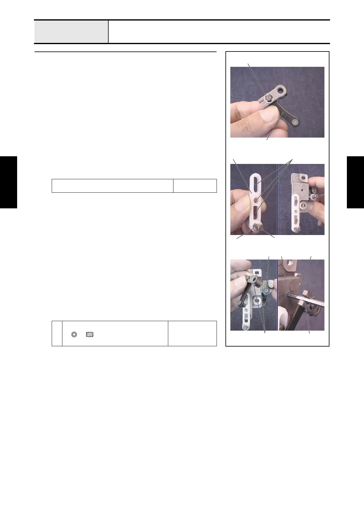
13 Driving jump assembly (2)
*Key point
• Use a positioning pin (one of adjustment jigs).
1. Thread the plain washer M5 through the differential lever, attach the
differential lever to the J link assembly 1, and then attach the retaining
ring E4.
2. Thread the J slide lever shaft 3 through the J slide lever 2, and then
attach the retaining ring E4.
3. Apply MOLYKOTE EM-30L to the 3 holes 4 on the J slide lever
assembly.
4. Attach the J slide lever assembly to the 2 shafts of the J base assembly.
5. Thread the thrust washer onto the shaft 5 of the J driving lever, and attach
the J differential lever assembly while aligning it with the shaft of the J
driving lever and the hole on the J slide lever 2.
6. Thread the positioning pin 8 through the positioning hole 6 of the J base
assembly and the positioning groove 7 of the J link assembly, and then
tighten the 2 screws 1 to secure the J link assembly.
Apply MOLYKOTE EM-30L to the 3 holes on the J slide
lever assembly.
Size of a grain of
rice
1
Torque
0.59 — 0.78 N-m
Retaining ring E4
5
4
3
6
1
1
Retaining ring E4
2
8
7
Set Screw, Socket (CP)
M3X4

 Loading...