3 - 35
Main unit
Upper shaft unit
Assembly
Assembly
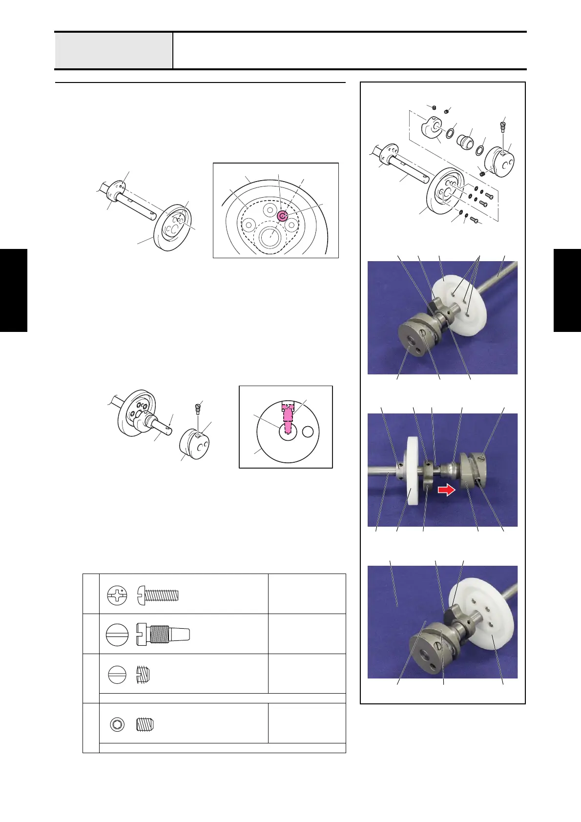
1 Upper shaft assembly
1. Set the presser foot cam 1 to the presser foot cam collar 2.
*Key point
• Check that the center of the positioning hole 3 of the presser
foot cam 1 is the same as the center of the positioning hole
4 of the presser foot cam collar 2.
2. Secure the presser foot cam 1 and the presser foot cam collar 2 with the 3
washer plains S4 5 the 3 spring washers 6 and the 3 screws 1.
3. Insert the balancer 7, the washer, thrust 8, the upper shaft metal 9, the
washer, thrust 0 and the thread take-up cam A into the upper shaft B in
this order.
*Key point
• Check that the cut surface C of the balancer 7 is the
direction side of the upper shaft metal 9.
4. Align the positioning hole D of the thread take-up cam A with the
positioning hole E of the upper shaft B, and then insert the shaft position
of the screw 2 into the positioning hole E, and then tighten the screw 2.
5. Tighten the screw 3.
6. Slide the balancer 7 to the direction of the allow, and then secure it with
the screw 4.
*Key point
• Check that align the screw 4 with the D cut surface F of the
upper shaft B.
• Check that the upper shaft metal 9 is not a wobble, and it
moves smoothly.
7. Tighten the screw 5.
1
Torque
2.15 N-m
2
Torque
2.94 — 3.92 N-m
3
Torque
1.97 — 1.76 N-m
Flat-blade screwdriver
4
5
Torque
0.49 N-m
Hex wrench 2.0 mm
2
3
1
5
4
A
6
5
1
B
2
0
9
8
7
1
A
1
F4
4A
7 B
C
9
2
2
3A
9
71
2
7
59 1
B
4
3
2
2
1
1
3
4
2
2
A
B
E
D
B
A
Screw, Pan
M4X12
Screw
Set Screw (CP)
SM6.35
Set Screw, Socket (CP)
M5X6

 Loading...