3 - 29
Power unit
Main unit
Assembly
Assembly
3
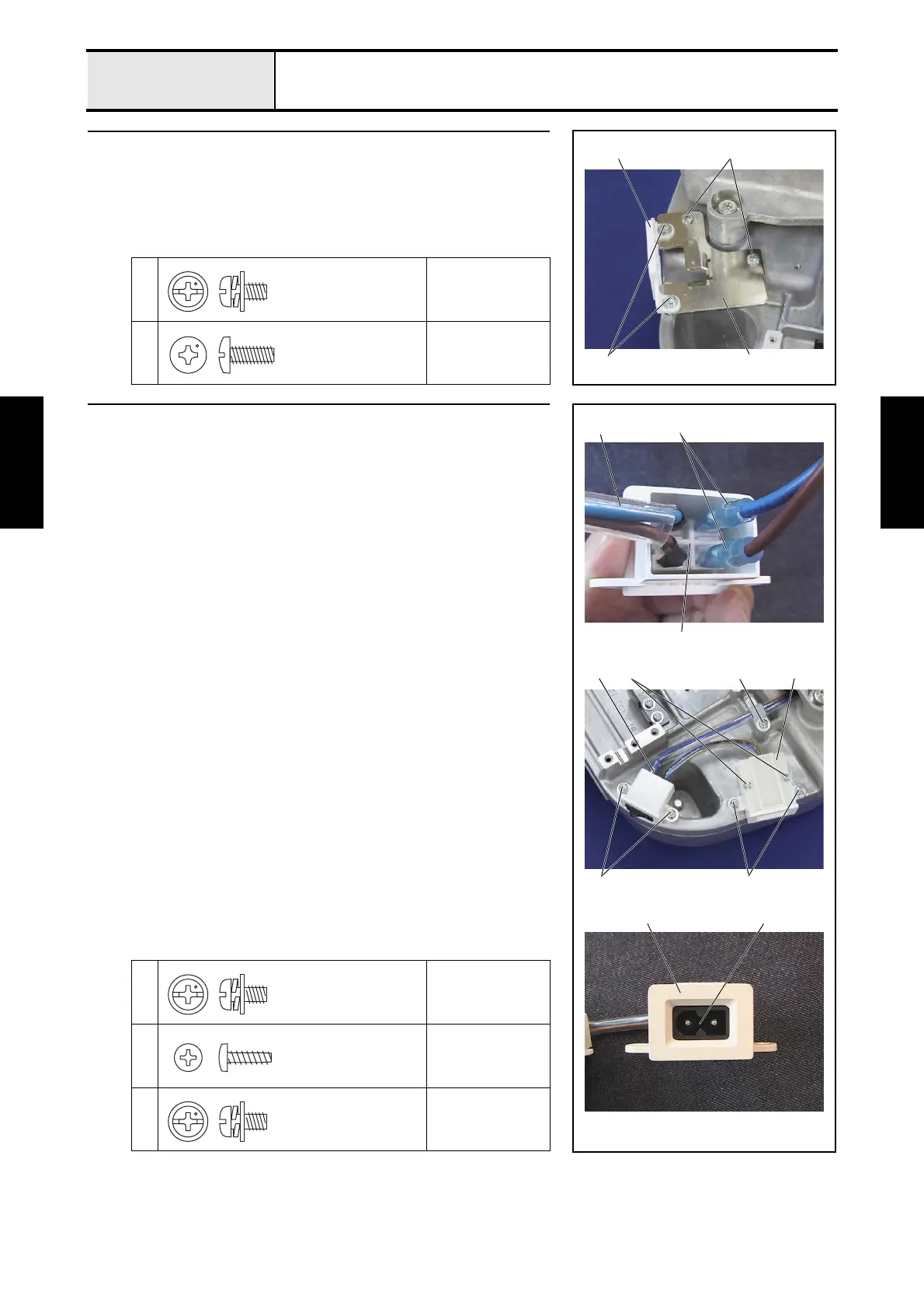
EX connector holder attachment
1. Attach the EX connector holder cover 1 to the EX connector holder 2
with the 2 screws 1.
2. Attach the EX connector holder 2 to the base frame with the 2 screws 2.
1
Torque
0.78 — 1.18 N-m
2
Torque
1.47 — 1.96 N-m
1 2
1
2
Screw, Pan (S/P washer)
M4X8
Taptite, Bind S
M4X10
4 Power switch assembly and inlet attachment
1. Connect the free end of the 2 power lead wire assemblies 1 (one end is
connected to the power PCB assembly) to the power switch assembly 2.
*Key point
• Connect each of the power lead wires to the terminal adjacent
to the rocker switch lead wire 5 of the same color.
2. Attach the power switch assembly 2 to the base frame with the 2 screws
1.
3. Attach the inlet cover 3 to the base frame with the 2 screws 2.
4. Place the power switch assembly's rocker switch 4 in the inlet cover 3
(pay attention to the direction), and then attach the inlet cover lid with the 2
screws 3.
5. Attach the power lead wire assembly to the base frame with the screw 4
and the cord clamp (NK-6N).
1
2
Torque
0.78 — 1.18 N-m
3
Torque
0.39 — 0.78 N-m
4
Torque
0.78 — 1.18 N-m
1
2
4
3 3
1
2
5
2
3
4
Screw, Pan (S/P washer)
M4X8
Taptite, Bind B
M3X10
Screw, Pan (S/P washer)
M4X8
 Loading...