3 - 78
Main unit
Feed unit
Assembly
Assembly
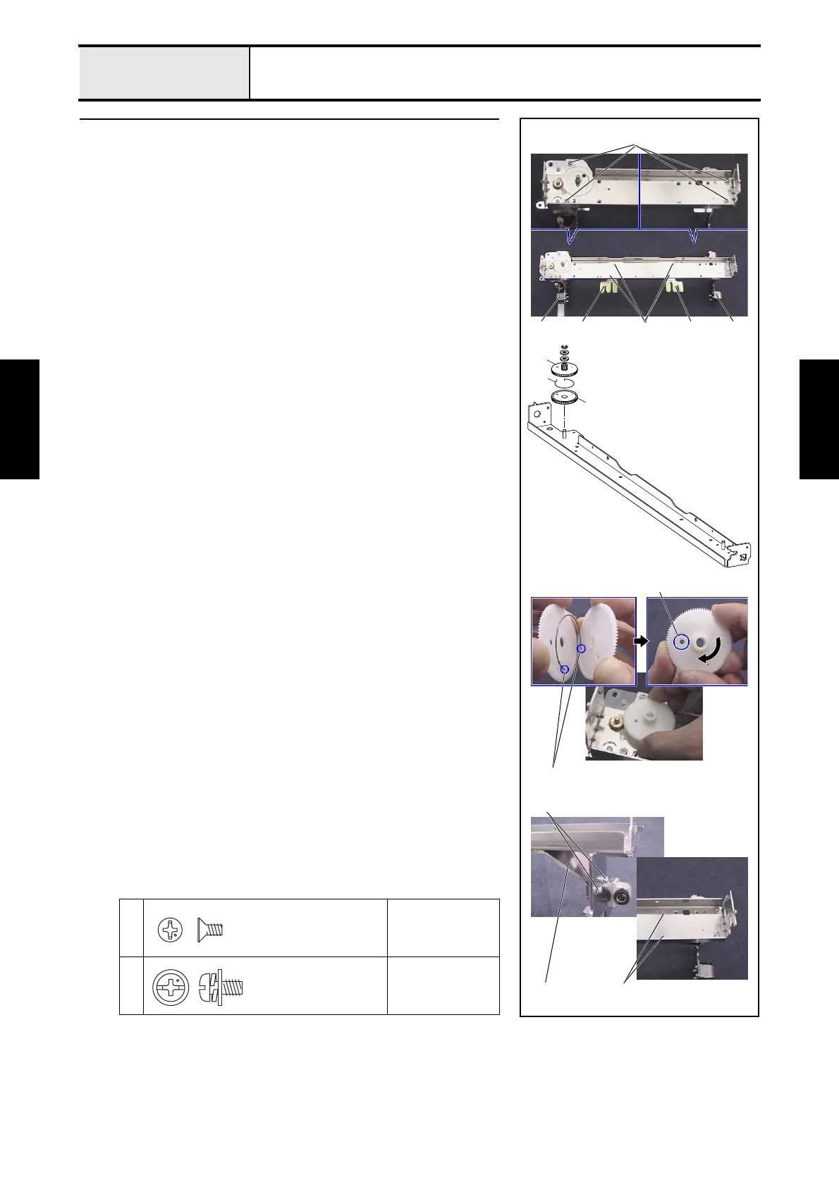
4 Feed frame assembly
1. Attach the cylinder connection L/R 1 to the feed frame with the 4 screws
1.
2. Temporarily attach the Y-carriage R assembly 2 and the Y-carriage L
assembly 3 to the feed frame assembly with the 4 screws 2.
3. Attach the Y-driving gear pulley B 4, gear spring 5, Y-driving gear
pulley A 6, washer, and plain washer (M6) (2 sets) to the gear pulley
shaft, and then attach the retaining ring E4.
*Key point
• Attach the gear spring 5 to the small hole 7 on Y-driving gear
pulleys B 4 and A 6.
• Turn Y-driving gear pulley A 6 clockwise until the large hole
8 on Y-driving gear pulley A 6 is aligned with the large hole
8 on Y-driving gear pulley B 4. Engage the pulleys with the
X-motor gear, and attach them to the shaft.
4. Temporarily attach Y-carriage RB 9 to the feed frame and Y-carriage R
with the 2 screws (3 4, 2 each).
5. Adjust the position of the X-motor assembly so that the backlash of the X-
motor gear and the Y-driving gear pulley assembly is zero.
1
3
Torque
0.78 — 1.18 N-m
2
4
Torque
1.18 — 1.57 N-m
6
5
4
2
8
3
7
211 1
4
9 3
Screw, Flat
M3X6
Screw, Pan (S/P washer)
M4X8

 Loading...