EasyManuals Logo

Brother PR655 Service Manual

Brother PR655
341 pages
To Next Page IconTo Next Page
To Previous Page IconTo Previous Page
Page #19 background imageLoading...
Page #19 background image
1 - 8
Outline of Mechanism
Outline of
Mechanism
Outline of
Mechanism
Layout for P.C.B. connectors
The illustration below shows layout for Printed Board connectors.
îš„ Main P.C.B.
Connector Pins
Pin # : 1
Pin # : 5
51
CN12
PANEL
(Panel PCB)
71
CN10
SPOOL_R
* Not used
51
CN8
THRD
(Needle thread motor)
CN7
WIPER
(Wiper motor)
4
4
1
1
CN6
INDEX
(Index motor)
4
1
CN27
MOTOR
(Power supply
PCB_motor)
1
7
CN26
POWER
(Power supply
PCB_+40V.+24V)
CN5
PICKER
(Picker motor)
4
1
CN4
TRIM
(Thread cutter
motor)
4
1
CN3
LED
(LED light PCB)
4
1
CN2
UP_UNIT
* Not used
5
1
CN1
BOT_UNIT
(Extension I/F
PCB_L)
5
1
CN24
YMOTOR
(Y motor)
1
4
CN23
XMOTOR
(X motor)
1
10
CN20
BRACE
* Not used
1
2
CN19
ENC
(Main shaft sensor)
1
6
CN18
PORG
(Picker sensor)
1
3
CN17
THREAD
(Needle thread
sensor)
1
3
CN16
WORG
(Wiper sensor)
1
3
CN15
IROT
(Color change
sensor)
1
3
CN14
IORG
(Index sensor)
1
3
CN13
TORG
(Thread cutter
sensor)
1
3
CN22
ISP
* Not used
1
6
CN21
RHOOK
* Not mounted
CN25
MODE
* Not used
1
5
CN11
SPOOL_L
* Not used
51
14
CN9
HEAD
(Head PCB)
81

Table of Contents

Other manuals for Brother PR655

Questions and Answers:

Question and Answer IconNeed help?

Do you have a question about the Brother PR655 and is the answer not in the manual?
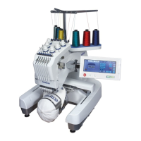
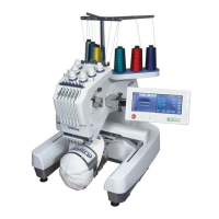
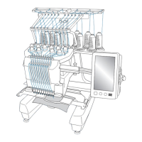
Brother PR655 Specifications

General IconGeneral
Number of Needles6
Built-in Designs25
USB PortYes
LCD DisplayYes
TypeEmbroidery Machine
Built-in Fonts28
Maximum Speed1000 stitches per minute
Embroidery Area300mm x 200mm

Related product manuals