3 - 24
Thread cut unit
Main unit
Assembly
Assembly
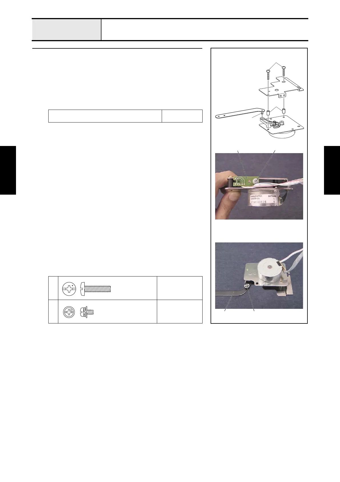
2 Cutter unit assembly (Step 2)
1. Attach the cutter bracket assembly and the 2 collars 1 to the CT motor
bracket assembly with the 2 screws 1.
2. Attach the thread cutter sensor assembly (white) 2 to the CT motor
bracket assembly with the screw 2.
3. Apply MOLYKOTE EM-30L to the level link assembly's shaft 3.
4. Attach the lever link assembly 4 to the lever gear, and then attach the
retaining ring E2.
Apply MOLYKOTE EM-30L to the lever link assembly's
shaft.
Size of a grain of
rice
1
Torque
1.18 — 1.57 N-m
2
Torque
0.57 — 0.78 N-m
1
1
3
4
2 2
Retaining ring E2
Screw, Bind
M4X16
Screw, Pan (S/P washer)
M3X6

 Loading...