Failure Investigation for Electronic Parts
Failure Investigation
for Electronic Parts
Failure Investigation
for Electronic Parts
5 - 8
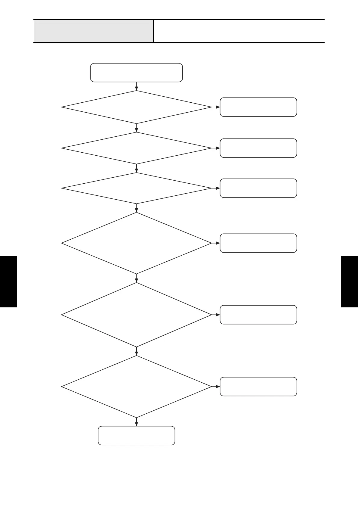
The needle bar does not move normally.
The needle bar does not move normally.
Connect it properly.
N
Y
Y
Is the color change sensor's lead properly
connected to connecter CN15 on the main PCB?
Connect it properly.
N
Y
Is the index sensor's lead properly connected
to connecter CN14 on the main PCB?
Connect it properly.
Change the color change sensor.
N
Y
Is the index motor's lead properly connected
to connector CN8 on the main PCB?
N
Y
Does the voltage between pins 1 and 3 of
connector CN15 on the main PCB vary from
0 to 3V at each needle bar position when
the index motor's gear is rotated by hand?
Change the index sensor.
N
Y
Does the voltage between pins 1 and 3 of connector
CN14 on the main PCB vary from 0V at the position of
the 1st needle bar to 3V at the position of the 2nd needle
bar when the index motor's gear is rotated by hand?
Change the index motor.
N
Is the resistance between pins 1 and 2,
and 3 and 4 of the index motor 5.1 - 6.1Ω,
respectively, when the motor's connector
(CN6) is removed from the main PCB?
Change the main PCB.

 Loading...