Measure with the arm
H00007091 - Absolute Arm User Manual │Version 5.2.0 (2019-03-07) │133
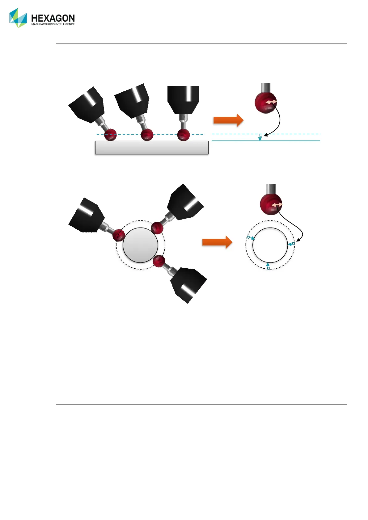
Probe radius compensation
When probing, the software uses the centre ball point coordinates for feature calculation, not the contact
point. The software then calculates the feature that has been selected and adds or compensates for the
probe radius:
• For a plane, it consists by translating the plane along its own vector with the radius value
• For a circle, cylinder, sphere, or similar item, it consists by adding or subtracting the probe diameter to
the feature diameter.
• For a surface inspection point, it consists by translating the point along the nominal surface vector with
the radius value
• For a simple 3D point, there is no way to know the contact side and so no compensation is possible.
• Even if the probe doesn’t need to be perpendicular to the surface, a minimum orientation of the probe
is necessary to get correct probe radius compensation: the probe has to point toward the material.
Please refer to the applicable measurement software user manual for more details about probe
compensation.
Measurement best-fit
Except for individual points features (single point, surface points …) each geometric feature is calculated
using a specific method (least square, minimum radius …). Once the feature is calculated, each probe point
is compared to the result feature, to get the shape error (flatness, circularity …). Most of the software can
give the maximum error value, after each new point once the feature is validated. This maximum error value
(“best-fit”) gives very useful information to make sure that the feature has been correctly probed.
 Loading...