Home
Hexagon
Robotics
Absolute Arm RS5
Hexagon Absolute Arm RS5 User Manual
5
of 1
of 1 rating
234 pages
Give review
Manual
Specs
To Next Page
To Next Page
To Previous Page
To Previous Page
Loading...
Installation
H00007091 - Absolute Arm
User Manual
│
Version 5.2.0 (
2019
-
03
-
07
)
│
77
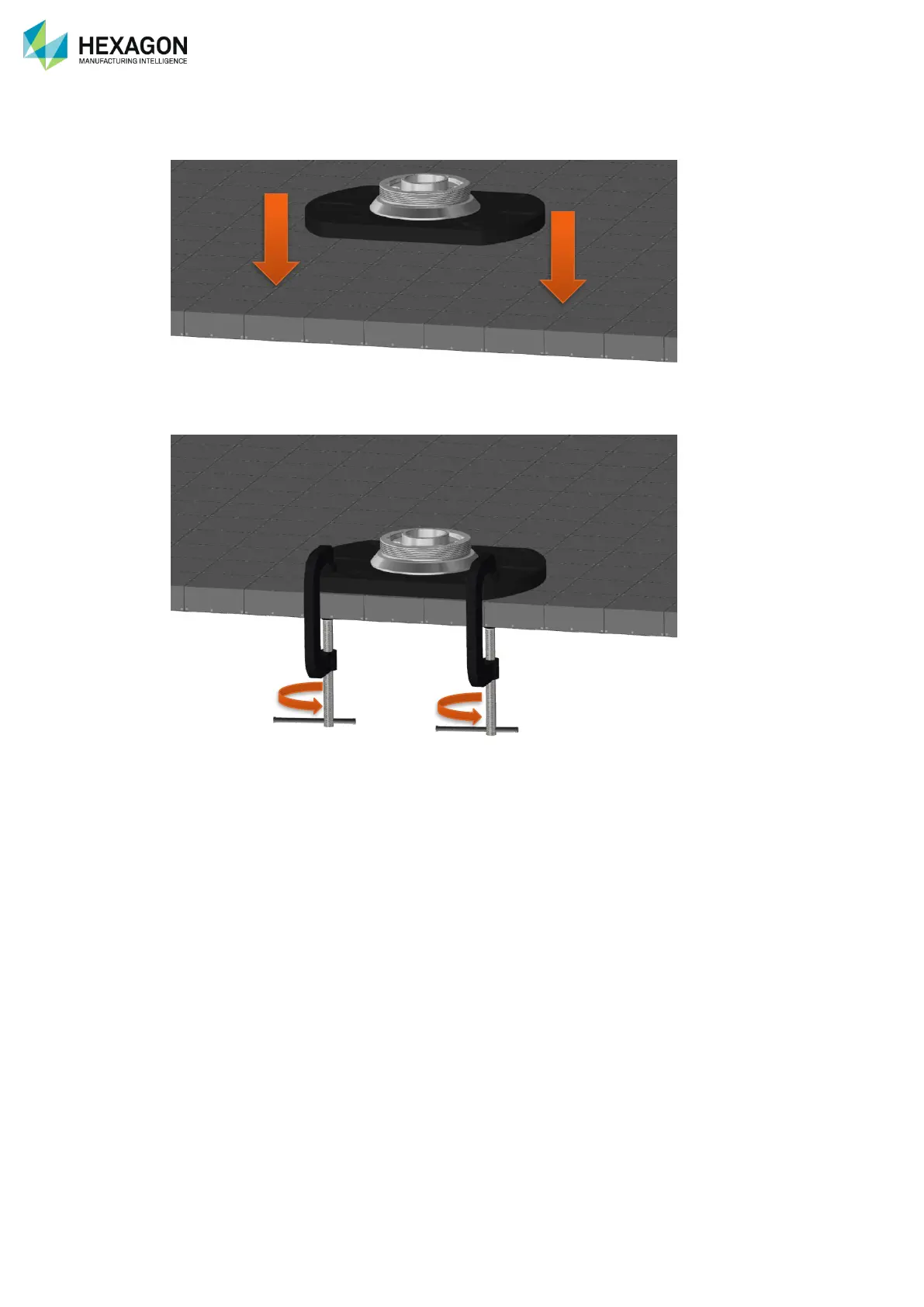
D.1.3
STANDARD BASE-PLATE
1.
Place the plate on a level and stabl
e surface.
Fig.
28
: Mounting plate installation
2.
Fix it in place (using C-
Clamps,
screws, etc…)
77
79
Table of Contents
Table of Contents
3
Introduction
5
Conventions Used in this Guide
6
Pictures in the Manual
6
Complete Documentation
6
Safety Note
7
Mechanical Safety
8
Battery Safety
9
Power Safety
9
Laser Safety
10
Other Safety Care
10
A.1 Overview
11
Absolute Arm Presentation
11
6 Or 7 Axes
11
6-Axis Wrist
12
7-Axis Wrist
12
Compact – 1.2 Size
12
Arm Wrist
12
Tube Inspection Arm
13
Rds
13
Levels and Features of Absolute Arm
14
Standard Accessories and Options
14
Size of Arms
17
Label Location on the A-Axis
18
Arm Identification
18
Label on the Arm
18
Label on the Case
18
Arm Label
19
Control Pack Identification
20
Control Pack Label
20
Scanner Identification
21
RS5 Label
21
Components Description
22
Absolute Arm 83 Series
22
B.1 Arm Description
22
Absolute Arm 85 Series
23
Absolute Arm 87 Series
24
Absolute Arm Compact 1.2
25
Machine Reference
26
Base Description
27
Front Panel
27
Back Panel - Control Pack
27
Base - Control Pack
27
Status Pictograms
28
Control Pack Connections
29
Adapter for HP-L-20.8 Scanning Pack
30
Battery Change on Control Pack
31
Level of the Batteries
32
Control Pack Change
33
FP4 Setup
35
Standard Cables
36
B.3 Cables - Communication
36
Connection/Disconnection of the Plugs
37
To Connect a Cable
37
Bluetooth Wireless Accessories
38
6Axes Wrist Description
39
7 Axes Wrist Description
40
Basic Wrist
41
Wrist Description
41
Pistol Grip
42
Change the Size of Hand Grip
43
Remove/Mount the Pistol Grip
44
Wrist Display
45
Connection
45
Status
45
Quick Access Menu
46
Screen Saver
46
Mount / Remove the Nose Cone
47
Integratd Laser Line Scanner - RS5
48
Mount the Scanner
49
Status Indicator
50
Remove the Scanner
50
SE Configuration
51
Mount Scanners or Probes on the Offset Location
52
Contact Probes
53
B.6 Standard Probes
53
Other Kind of Contact Probes
54
Non-Contact Tube Probes
55
Buttons
55
Identification (Serial Number)
55
Laser Guidance
56
Sounds
56
Sizes of Probes and Tubes
56
Mount the Probe on the Arm
57
Gas Pump Counterbalance Locking System
58
B.7 Counterbalance
58
Smartlock
59
Home Dock
60
Counterweight
61
Setup
61
Dismounting
61
Inside Components
62
B.8 Travel Case
62
Accessories Case
64
Control Pack
65
Hp-L-20.8
65
Leds - Sensor
65
External Laser Scanners
65
Hp-L-8.9
66
Power-On / Warm-Up / Status LED
66
RDS Software Package
67
Prerequisites
67
C.1 Presentation
67
Software Setup
67
C.3 RDS Agent
70
Components
70
Description of the Interface
70
RDS Agent
70
Shortcuts
71
RDS Messages
72
Connection Messages
72
Warning Messages
72
Other Messages
72
Installation
73
Standard Base-Plate
73
Standard Magnetic Base
73
D.1 Mounting Base
73
Fix with Screws
74
Absolute Arm Compact 1.2 Base
74
Default Use
74
Use Magnetic Anchors
75
Use Magnets
76
Mounting Ring
77
Mounting Plate Installation
78
Circular Magnetic Base
79
Standard Magnetic Support Installation
79
Vacuum Base
80
Quick Installation
80
Special Raisers
81
Raisers on Magnets
81
Heavy Duty Stands
82
Stands
82
Light Tetralock Portable Stand
82
M-Series Carbon Graphite Portable Stand
83
Recommendations about Handling the Arm
84
2.0M to 4.5M Arms
84
D.2 Arm Installation
84
Carry an Absolute Arm Compact 1.2
85
Extract the Arm from the Case
86
Setup the Arm
87
Absolute Arm Compact
87
Absolute Arm (2.0 to 4.5)
88
Absolute Arm Compact (1.2)
89
Pack the Arm
89
Arm Tube Raisers
91
Arm Tube Installation-Uninstallation
91
Tube Inspection Arm Installation
91
Available - Effective Connections
92
E.1 Common Features
92
Power Battery
93
Power Supply
93
Battery
93
Power Supply Connection
93
TCP/IP Access Detail
94
How to Access the Network Settings
95
Arm Setup
96
RDS Setup
96
USB Connection (Arm Only)
96
USB + Scanner Connection
97
USB Connection (Arm + Integrated Scanner)
97
Computer Setup for the Scanner
98
Note about Wi-Fi
99
Customized Setup - Authorized Channels
99
Wi-Fi Advanced Settings
99
Wireless Connection (Arm / Scanner)
99
Wireless Connection
100
Computer Setup
102
Ethernet Connection (Arm / Scanner)
103
External Scanners Connection
106
Hexagon HP-L-20.8 Scanner
107
Hardware Connection
107
Leds
109
Management Software
109
Hexagon HP-L-8.9 Scanner
110
Hardware Setup
110
Perceptron V5 Scanner
112
Cables Connection
113
Scanner Qualification
114
Software Installation
114
Sphere Calibration
115
Measure with the Arm
116
Standard Rest Positions
116
Secured Rest Position
116
How to Use the Arm
116
Holding the Arm
117
Hand Grips (85 / 87 Series)
118
Counterbalance
118
Orientation and Limits of the Axes
119
Tube Inspection Arm Handling
120
Carrying the Arm
121
On SE / si Arm
123
On a 6 Axes Arm
123
How to Use the Arm Remote Mouse
123
Activate / Deactivate the Remote Mouse
124
How to Use the Arm Buttons
125
Trigger Button
125
3-State Button
125
Haptic Feedback
126
How to Interpret the Arm Sounds
126
F.2 Wrist Feedback
126
Available Actions
127
Activation/Navigation
127
Description of the Menu
127
Quick Access Menu
127
Probes Recognition and Alignment
128
How to Use Contact Probes
128
Use the Contact Probe
129
Touch Triggering Probe
129
Probing Tips and Tricks
130
Which Tip Diameter to Use
130
Probe Orientation
131
Number of Points to Probe
132
Location of Probed Points
133
Probe Guidance
133
Probe Radius Compensation
134
Measurement Best-Fit
134
Stylus Change
135
Contact Probe Alignment
136
Principle
136
Alignment Short Description
136
Contact Probe Verification
139
Volumetric Performance Test
139
Single Point Test
140
Sphere Diameter Test
140
Plane Test
140
End Measurement
141
Measuring a Tube
141
Straight Measurement
141
How to Use NC-Probes for Tube
141
Tube Probe Alignment
142
Artefact Properties
142
Vertical Tube Measurement
142
Horizontal Tube Measurement
143
Horizontal Tube Right Extremity Measurement
143
Horizontal Tube Left Extremity Measurement
143
Calculation
144
Tube Probe Verification
145
Start/Stop Scan
146
Warm up
146
How to Use Scanners
146
How to Handle and Digitize
147
Scanner Handling
147
Scanning Window
148
Camera Distance
149
RS5 Field of View
150
Scanning Z-Scales
150
Scanning Tips and Tricks
152
Speed
152
Points Density
152
Total Reflection
153
Shadow Fields
153
Over Exposure
153
Camera Orientations
153
Secondary Reflection
154
Edges
154
Hexagon Scanners Common Settings
155
Scanning Profiles
156
Save a Profile
156
Use a Profile
156
Sampling Filters
157
Exposure Modes
158
Manual Setup
158
Capture the Exposure
159
Manage the Exposure through the Quick Access Menu
159
Scanning Modes HP-L-20.8
160
Gain-Quality Filter
160
Hexagon Scanners Alignment
161
New Scanner
161
Run the Script
161
Reference Sphere
162
Use Scanner
162
Field Measurement
163
Global Sphere Measurement
164
Connect an Accessory
165
Use the Accessory
165
Bluetooth Wireless Accessories
165
G.2 Wi-Fi Chipset Configuration
166
Description of the Kit
167
Mounting Ring Kit (1.2 Series - Option)
167
Maintenance and Troubleshooting
169
H.1 10 Years Serviceability
169
10 Years Serviceability
169
Measurement Arm and Computer
170
Storage Place
170
Delivery of the Measurement Arm
170
Arm Storage, Use and Transport
170
H.3 Cleaning
171
Requirements
171
Cleaning the Scanner
171
Cleaning the Arm
171
Cleaning
172
Visual Inspection
173
Manual Inspection
173
Parts Replacement
173
H.4 Standard Maintenance
173
Accuracy Verification / Calibration
174
User Systematic Checking
174
Customer’s Periodic Control
174
RDS Procedures
174
H.6 WLAN Connection
175
H.7 Others
178
Appendix
181
I.1 Terminology, Symbols
181
Configuration for End-Software
182
Pc-Dmis
184
Tubeshaper
184
3Dreshaper
184
Contact Probing
184
Spatial Analyzer
185
Quindos7
185
Configuration for Probing
185
Probing Scan
185
Romost
186
Docs
186
Device Activation
187
Configuration for Contact Probe
187
Absolute Arm Settings
187
Polyworks
187
Configuration for Perceptron Scanner
188
Verisurf
189
Device Setup and Start
189
Activating a Device
190
Probe Management
191
Powerinspect
192
CMM Toolbar
193
Powershare
193
Configuration for Scanners
193
Configuration for Contact Probes
193
Metrolog/Μlog
194
Configuration for HEXAGON Scanners
195
Configuration for Perceptron
195
Geomagic
196
Configuration for Probing or HEXAGON Scanners
196
Aberlink3D
197
Configuring Aberlink3D
197
Using Aberlink3D
199
Calypso
201
Rhinoceros
202
Dimensions and Weights
203
Absolute Arm 2.0 to 4.5 Dimensions
203
Absolute Arm Compact 1.2 Dimensions
203
I.3 Technical Specifications
203
Arm Base
205
Travel Case Dimensions and Weights
205
Wrap Expedition Box
206
Absolute Arm Compact Base
207
Mounting Plate
207
Vacuum Mounting Base
208
Magnetic Base
208
Tube Inspection Arm Raiser
209
Tube Probes
210
Verifications Bars
211
ISO 10360-12 Probing Specifications
212
Absolute Arm 6-Axis Probing Accuracy and Size Specifications
212
Absolute Arm 7-Axis Probing Accuracy and Size Specifications
213
Absolute Arm -T Probing Accuracy and Size Specifications
213
ISO 10360-8 Annex D Scanning System Accuracy
214
Absolute Arm 7-Axis Scanning System Accuracy
214
Tube Probes Specifications
215
Acceleration
216
Permissible Environment Conditions
216
Temperature
216
CE Compliancy and Other Specifications
216
Wi-Fi
217
Bluetooth
217
Power Supply Specification Summary
218
CP2 / CP3 Battery Pack Specification Summary
220
Regulatory Information
220
Rohs2 Conformance
220
RS5 Scanner Specifications
221
Hexagon ® Scanners Specifications
221
RS5 Scanner Safety Care
222
Scan Mode Max Points Rate
223
Scan Mode Max Points
223
Scan Mode Pitch
223
HP-L-20.8 Scanner Specifications
223
Scan Mode Lines
224
Other Specifications
224
Warm-Up Time
224
HP-L-8.9 Scanner Specifications
225
HP-L-8.9 Scanner Compliance and Safety Care
227
Bluetooth Certified Equipment
229
European Union (and EEA) Only Recycling
231
I.7 Patents Details
232
I.8 Illustration Table
233
5
Based on 1 rating
Ask a question
Give review
Questions and Answers:
Need help?
Do you have a question about the Hexagon Absolute Arm RS5 and is the answer not in the manual?
Ask a question
Hexagon Absolute Arm RS5 Specifications
General
Brand
Hexagon
Model
Absolute Arm RS5
Category
Robotics
Language
English
Related product manuals
Hexagon RDS
208 pages
 Loading...