Issue 2.0
SV9100 Networking Manual 2-3
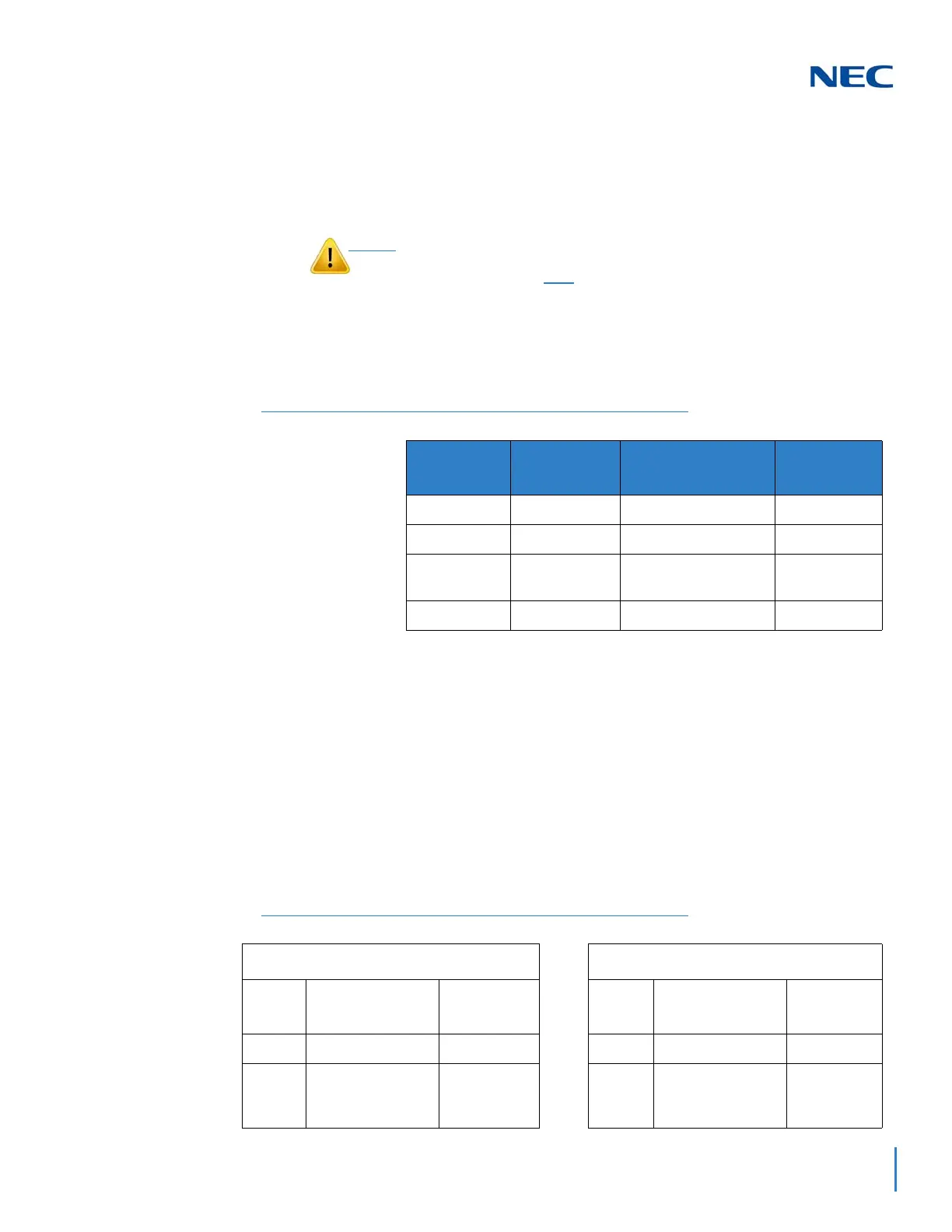
2.2 Order of Installing Extension Blades
The order in which the station blades (ESIU and SLIU) are
physically inserted determines the numbering plan.
For example, when a digital station blade (GCD-16DLCA) is in Slot #1 (ext.
301~316) and three additional digital station blades are installed in the following
order, the numbering plan below applies:
After the initial power up of the system, subsequent power ups or resets do not
change the slot identification. System programming (Program 90-05) must be
performed to change the slot identification.
Adding any daughter board to increase the available ports or going to a higher
capacity blade (e.g., GCD-16DLCA) may require that the slot be deleted in
programming, and the blade reinstalled. In the following example, to add a
daughter board to slot 2, the blade must be removed, deleted in
Program 90-05-01, then reinstalled with the daughter board attached, otherwise
the additional ports are not recognized. This however, uses new ports for the
combined blade – the initial ports (ports 17~24 using the example below) are not
used.
To avoid unexpected extension/trunk numbering if the VoIP or Voice
Mail Daughter Board register with the system first, install the
GCD-CP10 blade after
the other types of extension and trunk blades
are installed.
Table 2-1 Extension Blade Installation Order Example
Order of
Installation
Blade Slot
Number
Blade
Extension
Numbers
11
GCD-16DLCA
101~116
22
GCD-16DLCA
117~132
34
GCD-8DLCA
GPZ-8LCE
133~148
43
GCD-8DLCA
149~164
Table 2-2 Adding Daughter Board to Chassis Example
Initial Blade Updated Blade
Blade
Slot #
Blade
Extension
Numbers
Blade
Slot #
Blade
Extension
Numbers
1 GCD-16DLCA 101~116 1 GCD-16DLCA 101~116
2
GCD-8DLCA
(no daughter
board)
117~124 2 — —
 Loading...


