Chapter 23 Setup Relating to Router Interface and Tally (Router/Tally)
1290
Router Interface Settings (Router Menu)
a) When Matrix Size is 8×1
b) When Matrix Size is 16×1
c) When Matrix Size is 32×1
Coupling external boxes
By coupling a number of external boxes, the number of inputs can be increased.
Here the example of coupling External Box1 and External Box2 is described.
1
In the Router/Tally >Router >External Box Assign menu, select [External
box1] from the <Device> group.
2
In the <Matrix Size> group, select [8×1].
3
Turn the knobs to make adjustments.
4
In the <Device> group, select [External box2].
5
In the <Matrix Size> group, select [32×1].
6
Turn the knobs to make adjustments.
At this point make the settings of Destination and Level the same as in step
3.
This automatically couples External Box1 and External Box2, forming an
external box with 40 (8+32) inputs.
Setting the group number of an S-Bus description name
1
In the <Alias Name Gp> group of the Router/Tally >Router menu, press
[Gp No].
2
Turn the knob to set the following parameter.
a) When setting values 1 to 7 are selected: If the name is not set, the description name for “0”
appears.
If the description name for “0” is not registered either, the Type and No values appear.
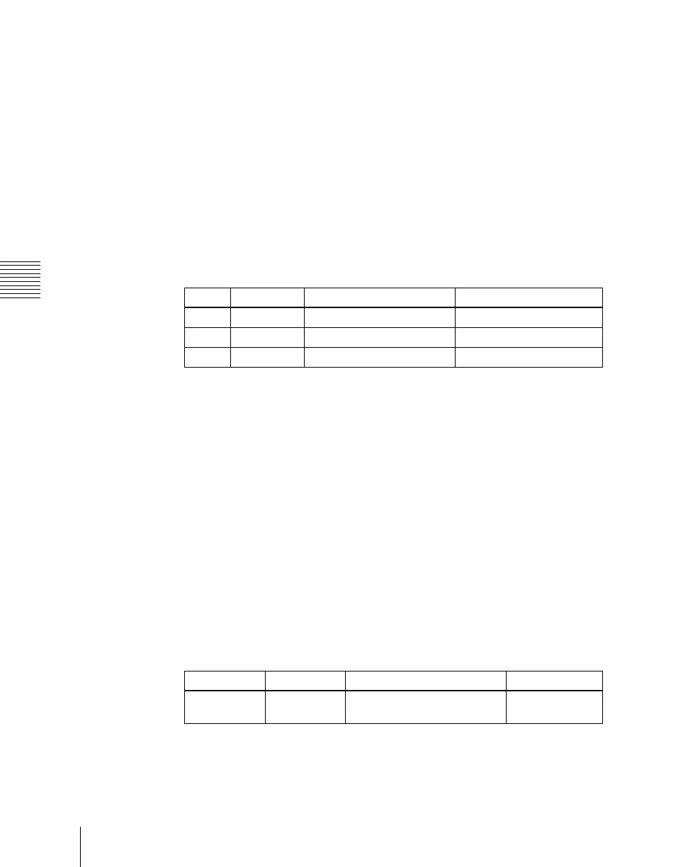
Knob Parameter Adjustment Setting values
1 Source Source start address 1 to 1017
2 Destination Destination start address 1 to 1024
3 Level Level 1 to 8
Knob Parameter Adjustment Setting values
1 Gp No Group number of S-Bus
description name
0 to 7
a)

 Loading...


