Chapter 12 External Devices
763
Control of GPI Devices
The “GPI Output” list (on the left) shows the relation between ports 1 to 8
for the GPI timeline and the trigger pulse output destination ports. The
content of this list is saved as keyframe data.
The “GPI Port” list (on the right) is for selecting the GPI trigger pulse
output destination.
2
Using either of the following methods, select the GPI timeline port you
want to set on the GPI Timeline.
• Press directly on the list on the left of the status area.
• Turn the knob.
3
Using either of the following methods, trigger output destination.
• Press directly on the list on the right of the status area.
• Turn the knob.
a) 1: Off (no specification)
2: Control panel (SCU) GPI port
3: DCU GPI port
4
If in step 3 you selected 2 (SCU) or 3 (DCU), then use the knob to select
the port number.
The indication for knob 3 depends on whether SCU or DCU is selected.
a) The number of DCU GPI ports depends on the settings in Engineering Setup.
The setting is reflected in the list on the right of the status area.
Notes
For the output port you have set here, be sure to set the trigger type to
“Rising Edge,” “Falling Edge” or “Any Edge.”
For details of the trigger type settings, see “Making Control Panel GPI
Output Settings” in Chapter 19 (Volume 3) and “Making DCU GPI
Output Settings” in Chapter 22 (Volume 3).
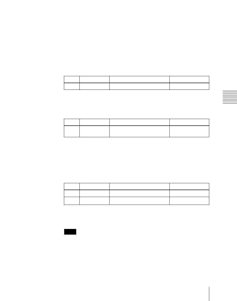
Knob Parameter Setting Setting values
1 GPI Output No GPI timeline port number 1 to 8
Knob Parameter Setting Setting values
2 GPI Port No SCU/DCU GPI port to be the
trigger output destination
1 to 3
a)
Knob Parameter Setting Setting values
3 SCU Port No SCU GPI port number 1 to 8
3 DCU Port No DCU GPI port number
1 to 50
a)

 Loading...


