7=2
(ECT
VOLTAGE)
• Before starting the inspection, check for loose or
poor contact
on
the ECT sensor 2P (Black)
connector and recheck the
OTC.
1.
ECT Sensor System Inspection
Turn the ignition switch
ON
and
engine stop switch
"0".
Check the ECT sensor with the MCS tester.
Is about 5 Vindicated?
YES -
GO
TO STEP
2.
NO
• Intermittent failure
• Loose or poor contact
on
the ECT
sensor 2P (Black) connector
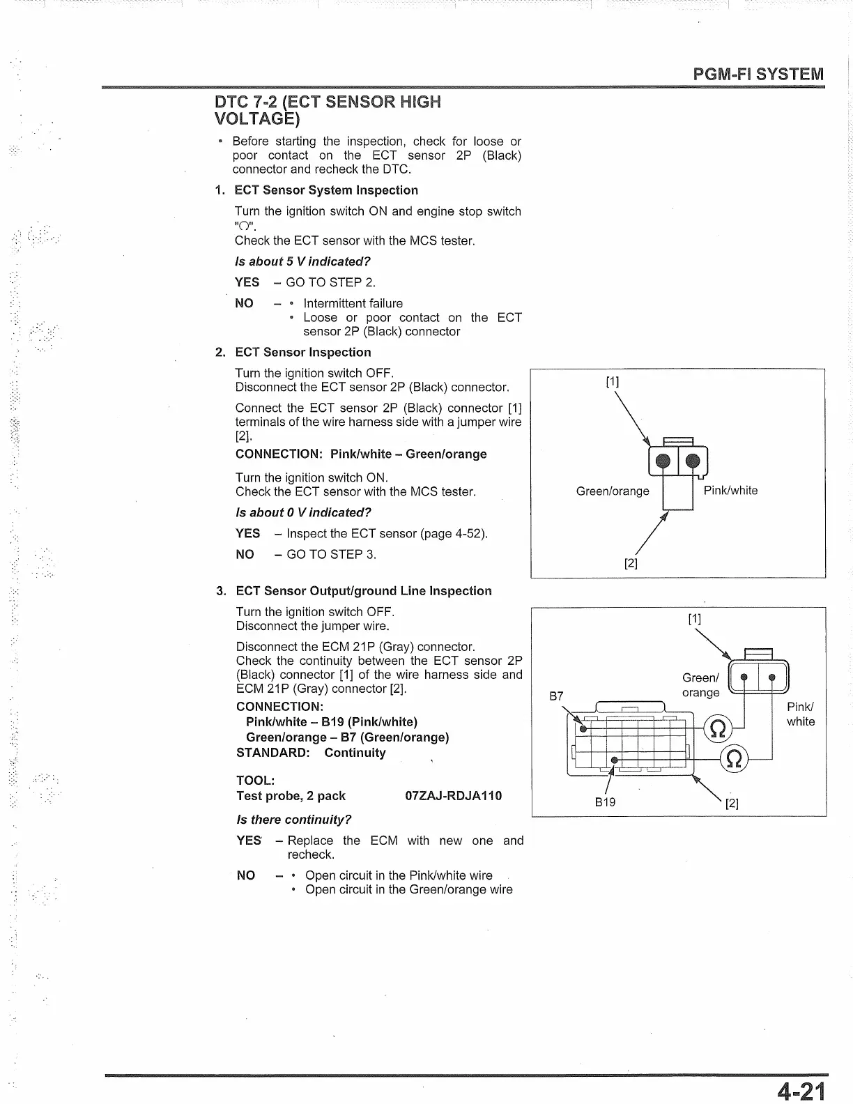
2. ECT Sensor Inspection
Turn the ignition switch OFF.
Disconnect the ECT sensor
2P
(Black) connector.
Connect the ECT sensor
2P
(Black) connector
[1]
terminals of the wire harness side with a jumper wire
[2].
CONNECTION: Pink/white - Green/orange
Turn the ignition switch
ON.
Check the ECT sensor with the MCS tester.
Is about O Vindicated?
YES - Inspect the ECT sensor (page 4-52).
NO
-
GO
TO STEP
3.
3. ECT Sensor Output/ground Line Inspection
Turn the ignition switch OFF.
Disconnect the jumper wire.
Disconnect the ECM
21
P (Gray) connector.
Check the continuity between the ECT sensor 2P
(Black) connector
[1]
of
the wire harness side and
ECM
21
P (Gray) connector
[2].
CONNECTION:
Pink/white -
819
(Pink/white)
Green/orange -
87
(Green/orange)
STANDARD: Continuity
TOOL:
Test probe, 2 pack
07ZAJ-RDJA 110
Is there continuity?
YES
- Replace the ECM with new one and
recheck.
NO - • Open circuit
in
the Pink/white wire
• Open circuit
in
the Green/orange wire
[1]
[2]
[1]
SYSTEM
Pink/
white
1
 Loading...