NOTE:
• When the
OTC
displays 1-1, 1-2, 8-1, 8-2, 9-1, or
9-
2,
check the following before
OTC
troubleshooting.
• Before starting the inspection, check for loose or
poor contact
on
the sensor unit
SP
(Black) connector
and ECM 33P (Black) connector.
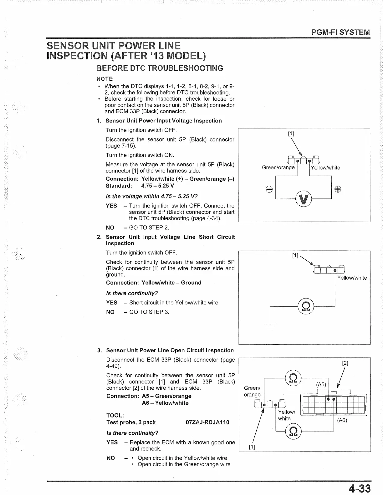
1. Sensor Unit Power Input Voltage Inspection
Turn the ignition switch OFF.
Disconnect the sensor unit
SP
(Black) connector
(page 7-15).
Turn the ignition switch
ON.
Measure the voltage at the sensor unit
SP
(Black)
connector
[1]
of the wire harness side.
Connection: Yellow/white(+) -
Green/orange(-)
Standard:
4.75-
5.25 V
Is the voltage within
4.75-
5.25
V?
YES - Turn the ignition switch OFF. Connect the
sensor unit
SP
(Black) connector and start
the
OTC
troubleshooting (page 4-34
).
NO - GO TO STEP
2.
2. Sensor Unit Input Voltage Line Short Circuit
Inspection
Turn the ignition switch OFF.
Check for continuity between the sensor unit
SP
(Black) connector
[1]
of the wire harness side
and
ground.
Connection: Yellow/white - Ground
Is there continuity?
YES - Short circuit
in
the Yellow/white wire
NO - GO TO STEP
3.
3. Sensor Unit Power Line Open Circuit Inspection
Disconnect the
ECM
33P (Black) connector (page
4-49).
Check for continuity between the sensor unit
SP
(Black) connector
[1]
and
ECM 33P (Black)
connector
[2]
of the wire harness side.
Connection:
AS
- Green/orange
AG-Yellow/white
TOOL:
Test probe, 2 pack
07ZAJ-RDJA
110
Is there continuity?
YES - Replace the
ECM
with a known good one
and
recheck.
NO - • Open circuit
in
the Yellow/white wire
• Open circuit
in
the Green/orange wire
SYSTEM
[1]
[1]
Yellow/white
[1]
 Loading...