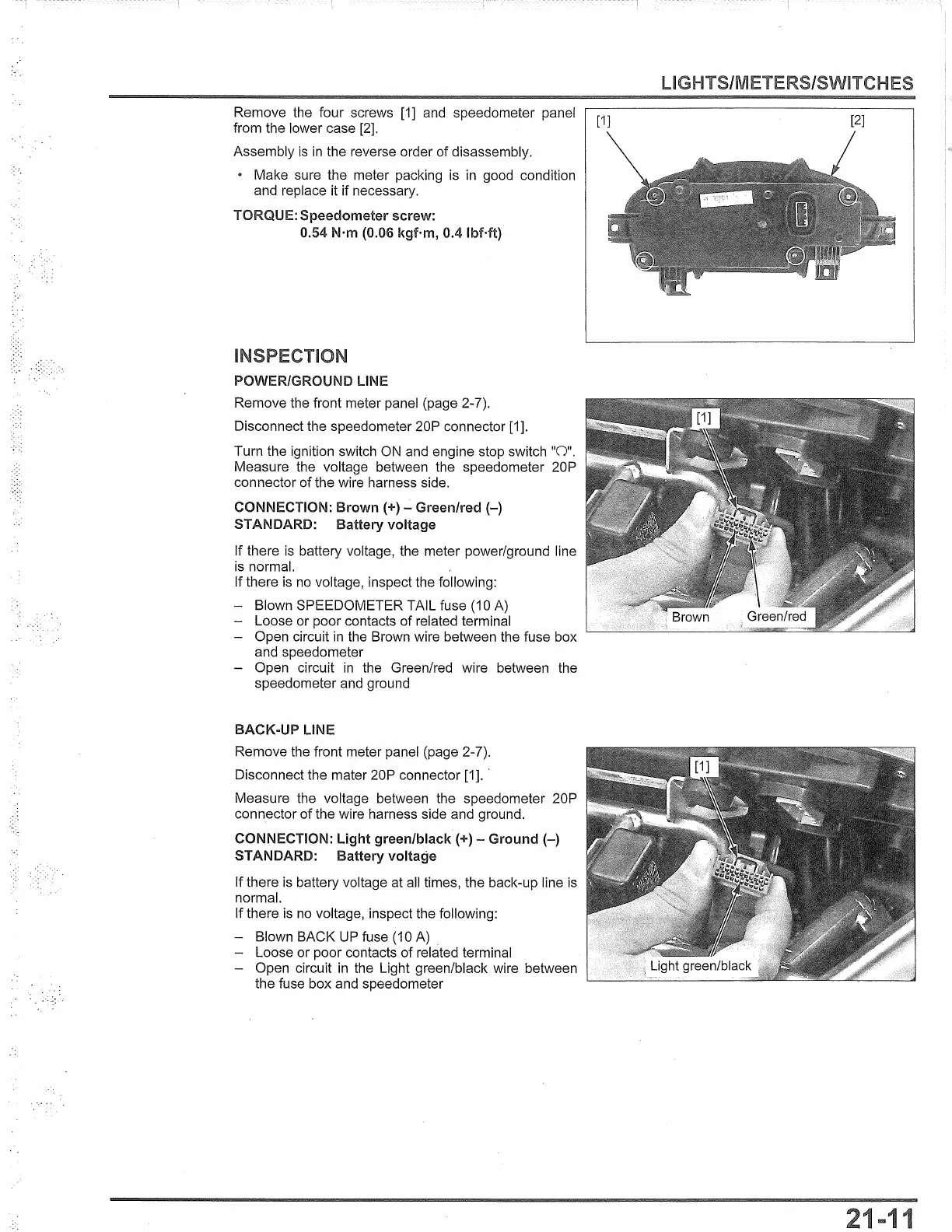
Remove the four screws
[1]
and speedometer panel
from the lower case [2].
Assembly
is
in
the reverse order of disassembly.
• Make sure the meter packing is
in
good condition
and replace it if necessary.
TORQUE:
Speedometer
screw:
0.54 N·m (0.06
kgf·m,
0.4
lbMt)
POWER/GROUND LINE
Remove the front meter panel (page 2-7).
Disconnect the speedometer 20P connector [1].
Turn the ignition switch
ON
and engine stop switch "O".
Measure the voltage between the speedometer 20P
connector
of
the wire harness side.
CONNECTION: Brown (+) - Green/red
(-)
STANDARD: Battery voltage
If there
is
battery voltage, the meter power/ground line
is
normal.
If there
is
no
voltage, inspect the following:
- Blown SPEEDOMETER TAIL fuse (10
A)
- Loose or poor contacts of related terminal
- Open circuit
in
the Brown wire between the fuse box
and speedometer
- Open circuit
in
the Green/red wire between the
speedometer and ground
BACK-UP
LINE
Remove the front meter panel (page 2-7).
Disconnect the mater 20P connector [1]. ·
Measure the voltage between the speedometer 20P
connector
of
the wire harness side and ground.
CONNECTION:
light
green/black(+) -
Ground(-)
STANDARD: Battery voltage
If there
is
battery voltage at all times, the back-up line
is
normal.
If there
is
no voltage, inspect the following:
- Blown BACK
UP
fuse (10 A) .
- Loose or poor contacts of related terminal
- Open circuit
in
the Light green/black wire between
the fuse box and speedometer
[1]
[2]
1
 Loading...