1 ENGINE
82410 • 82710 • 82910 WSM,
12271
Separating the Engine from Clutch Housing
1.
Disconnect the three point hitch delivery pipe and suction hose.
2.
Disconnect the glow plug lead wire and thermo sensor lead wire.
And then disconnect the connector for dynamo and starter motor
lead wire.
3.
Place the jack under the center frame.
4.
Hoist the engine by the chain at the engine hook.
5.
Remove the engine mounting screws and separate the engine
from the clutch housing.
(When reassembling)
• Apply liquid gasket (Three Bond 1208D or equivalent) to joint
face of the engine and clutch housing.
17.7 to 20.6 N·m
Engine mounting M8 screw
1.8 to
2.1
kgf·m
13.0 to 15.2 ft-Ibs
Tightening torque
48.1
to 55.8
N·m
Engine mounting M10 nut
4.9 to 5.7 kgf·m
35.5 to 41.2 ft-Ibs
12270S10180
Separating Front Axle Assembly
1.
Disconnect the radiator hoses (1).
2.
Remove the muffler pipe (2).
3.
Hoist the engine by the chain at the engine hook.
4.
Remove the front axle frame mounting screws and separate the
front axle assembly from the engine.
(1)
Radiator Hose
(2)
Muffler Pipe
12270S10190
Clutch cover mounting
23.5 to 27.5
N·m
Tightening torque
2.4 to 2.8 kgf·m
screw
17.4 to 20.3 ft-Ibs
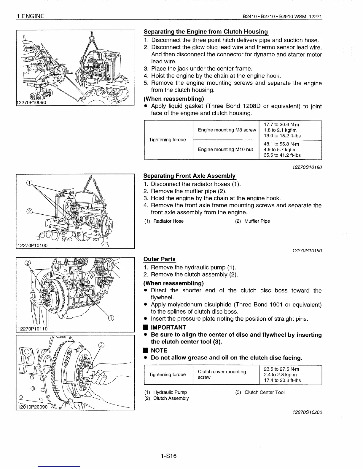
Outer Parts
1.
Remove the hydraulic pump (1).
2.
Remove the clutch assembly (2).
(When reassembling)
• Direct the shorter end of the clutch disc boss toward the
flywheel.
• Apply molybdenum disulphide (Three Bond
1901
or equivalent)
to the splines of clutch disc boss.
• Insert the pressure plate noting the position of straight pins.
• IMPORTANT
•
Be
sure to align the center of disc and flywheel by inserting
the clutch center tool (3).
• NOTE
•
Do
not allow grease and oil on the clutch disc facing.
(1)
Hydraulic Pump
(2)
Clutch Assembly
1-816
(3)
Clutch Center Tool
12270S10200
 Loading...


