82410 • 82710 • 82910 WSM, 12271
[5] FUEL SYSTEM
CHECKING AND ADJUSTING
(1)
Injection
Pump
1 ENGINE
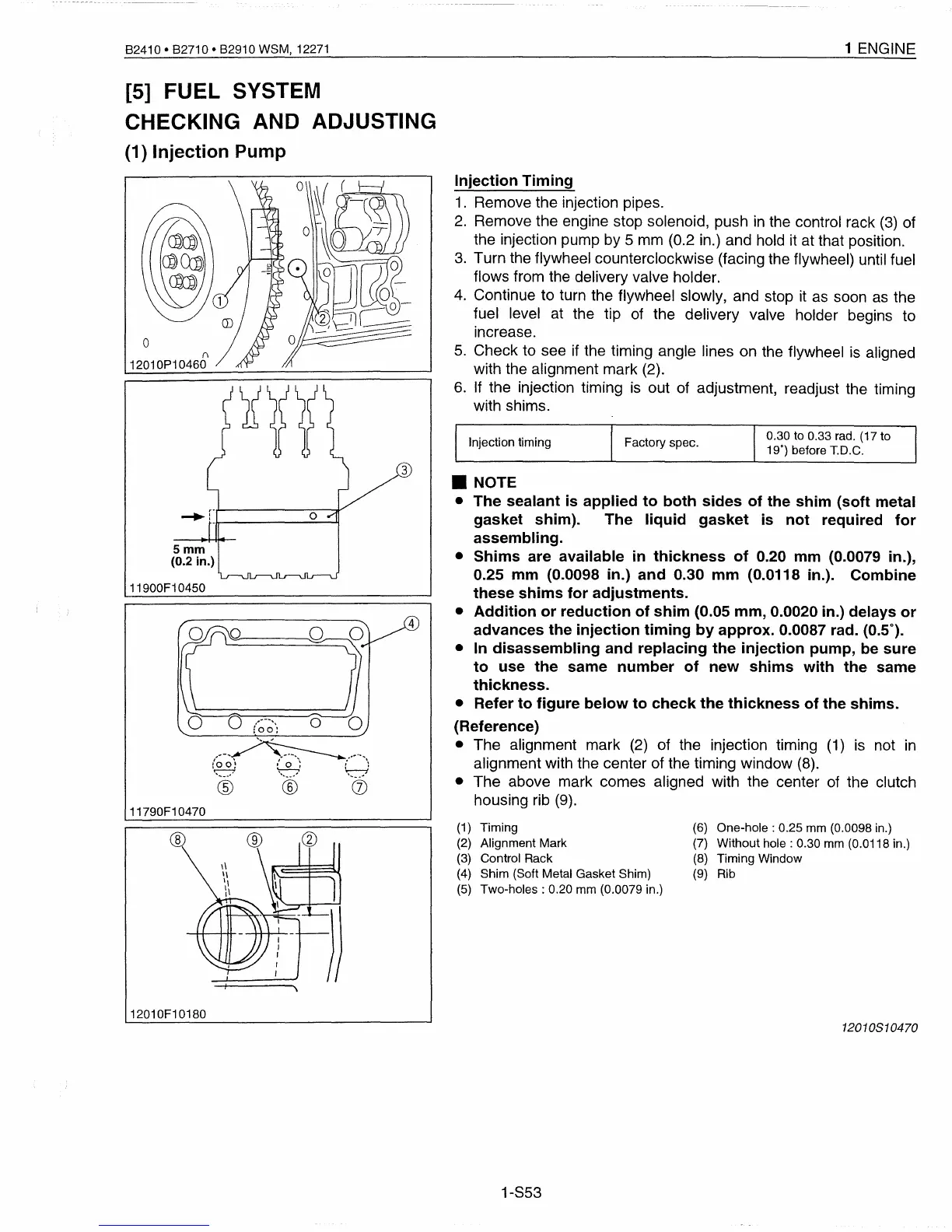
Injection
Timing
1.
Remove the injection pipes.
2.
Remove the engine stop solenoid, push
in
the control rack
(3)
of
the injection pump by 5 mm (0.2 in.) and hold it at that position.
3.
Turn the flywheel counterclockwise (facing the flywheel) until fuel
flows from the delivery valve holder.
4.
Continue to turn the flywheel slowly, and stop
it
as
soon
as
the
fuel level at the tip of the delivery valve holder begins to
increase.
5.
Check to see
if
the timing angle lines on the flywheel
is
aligned
with the alignment mark (2).
6.
If
the injection timing
is
out of adjustment, readjust the timing
with shims.
• NOTE
•
The
sealant
is
applied
to
both
sides
of
the
shim
(soft
metal
gasket
shim).
The
liquid
gasket
is
not
required
for
assembling.
•
Shims
are available
in
thickness
of
0.20
mm
(0.0079 in.),
0.25
mm
(0.0098 in.)
and
0.30
mm
(0.0118 in.).
Combine
these
shims
for
adjustments.
•
Addition
or
reduction
of
shim
(0.05
mm,
0.0020 in.) delays
or
advances
the
injection
timing
by
approx.
0.0087 rad. (0.5°).
• In
disassembling
and
replacing
the
injection
pump,
be
sure
to
use
the
same
number
of
new
shims
with
the
same
thickness.
• Refer
to
figure
below
to
check
the
thickness
of
the
shims.
(Reference)
• The alignment mark
(2)
of the injection timing
(1)
is
not
in
alignment with the center of the timing window
(8).
• The above mark comes aligned with the center of the clutch
housing rib
(9).
o
(\
12010P10460
5mm
(0.2 in.)
11900F10450
11790F10470
3
4
Injection timing
Factory spec.
0.30 to 0.33 rad. (17 to
19') before T.D.C.
12010F10180
(1)
Timing
(2)
Alignment Mark
(3) Control Rack
(4)
Shim (Soft Metal Gasket Shim)
(5)
Two-holes:
0.20 mm (0.0079 in.)
1-853
(6)
One-hole:
0.25 mm (0.0098 in.)
(7) Without
hole:
0.30 mm (0.0118 in.)
(8) Timing Window
(9) Rib
12010810470
 Loading...


