1 ENGINE
(1) Oil Pump
B2410 • B2710 • B2910 WSM, 12271
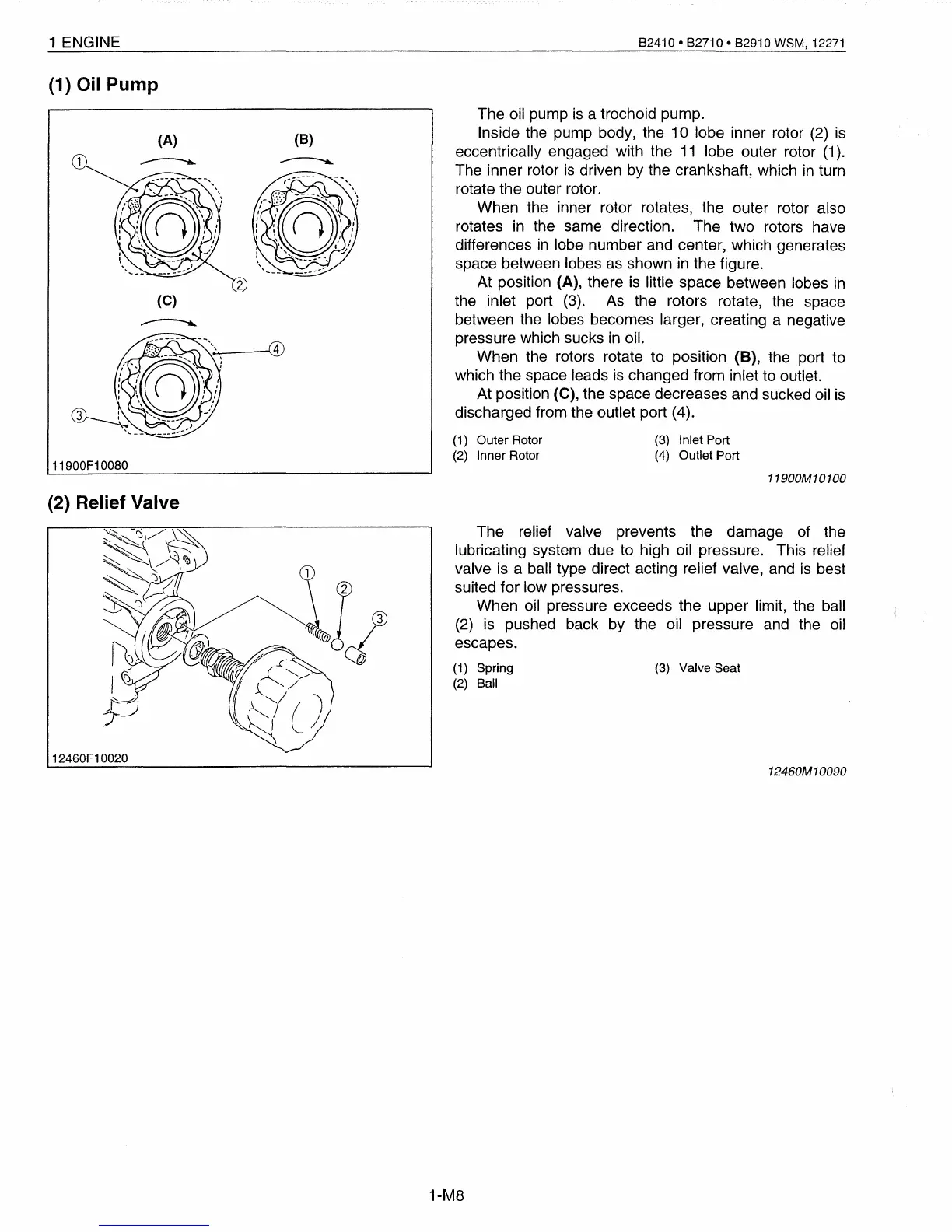
The
oil
pump
is
a trochoid pump.
Inside the pump body, the 10 lobe inner rotor
(2)
is
eccentrically engaged with the
11
lobe outer rotor
(1).
The inner rotor
is
driven by the crankshaft, which
in
turn
rotate the outer rotor.
When the inner rotor rotates, the outer rotor also
rotates
in
the same direction. The two rotors have
differences
in
lobe number and center, which generates
space between lobes
as
shown
in
the figure.
At position (A), there
is
little space between lobes
in
the inlet port
(3).
As
the rotors rotate, the space
between the lobes becomes larger, creating a negative
pressure which sucks
in
oil.
When the rotors rotate to position (B), the port to
which the space leads
is
changed from inlet to outlet.
At position (C), the space decreases and sucked oil
is
discharged from the outlet port (4).
The relief valve prevents the damage
of
the
lubricating system due to high oil pressure. This relief
valve is a ball type direct acting relief valve, and
is
best
suited for low pressures.
When
oil
pressure exceeds the upper limit, the ball
(2)
is
pushed back by the oil pressure
and
the
oil
escapes.
(A)
(C)
11900F10080
(2) Relief Valve
12460F10020
,---(1)
(8)
(1)
Outer Rotor
(2)
Inner Rotor
(1)
Spring
(2)
Ball
1-M8
(3)
Inlet Port
(4) Outlet Port
(3)
Valve Seat
11900M10100
12460M
10090
 Loading...


