3 TRANSMISSION
B2410·
82710·
B2910 WSM,
12271
Center section mounting
48.1
to 55.8
N·m
Tightening torque
hex. socket screw
4.9 to 5.7 kgf·m
35.5 to 41.2 ft-Ibs
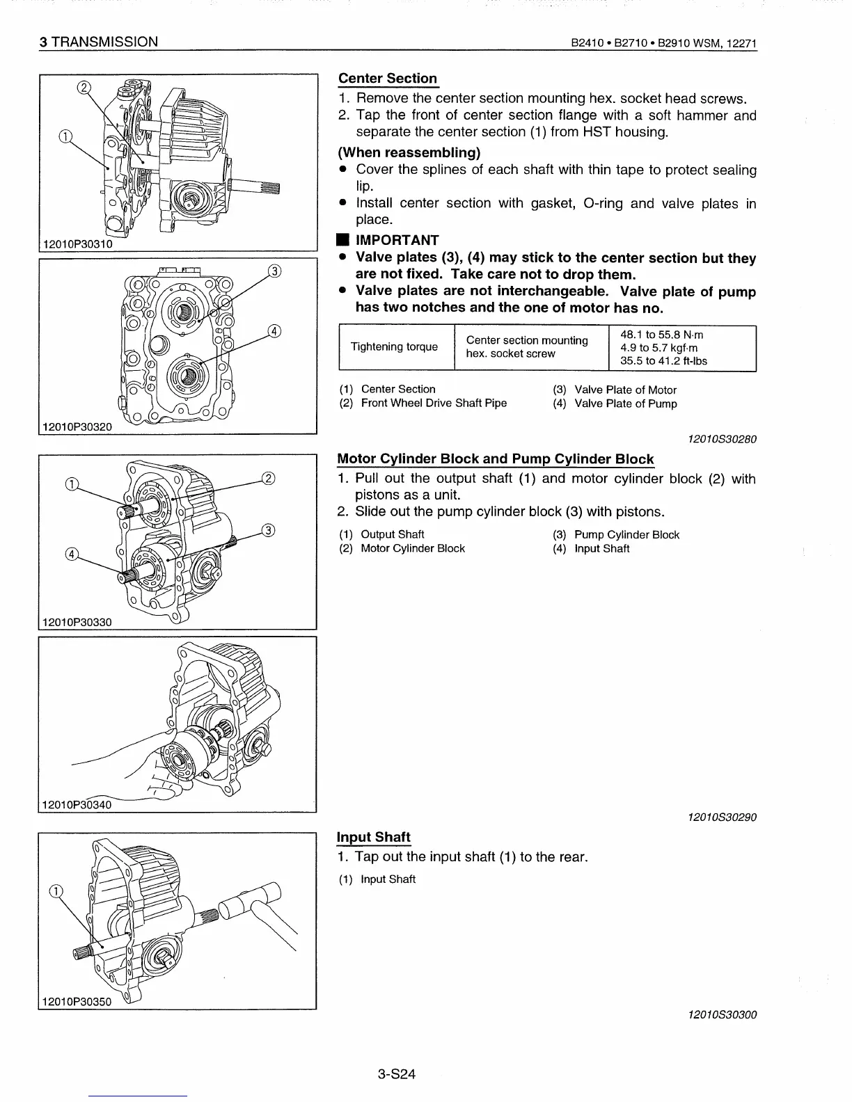
Center Section
1. Remove the center section mounting hex. socket head screws.
2. Tap the front of center section flange with a soft hammer
and
separate the center section (1) from HST housing.
(When reassembling)
• Cover the splines of each shaft with thin tape to protect sealing
lip.
• Install center section with gasket,
a-ring
and valve plates
in
place.
• IMPORTANT
• Valve plates
(3), (4) may stick to the center section but they
are not fixed. Take care not to drop them.
• Valve plates are not interchangeable. Valve plate of pump
has two notches and the one of motor has no.
12010P30310
12010P30320
(1
) Center Section
(2) Front Wheel Drive Shaft Pipe
(3)
Valve Plate of Motor
(4)
Valve Plate of Pump
120
1OS30280
12010P30330
Motor Cylinder Block and Pump Cylinder Block
1.
Pull out the output shaft (1) and motor cylinder block
(2)
with
pistons as a unit.
2.
Slide out the pump cylinder block (3) with pistons.
(1)
Output Shaft
(3)
Pump Cylinder Block
(2)
Motor Cylinder Block
(4)
Input Shaft
1201OS30290
Input Shaft
1.
Tap out the input shaft
(1)
to the rear.
(1) Input Shaft
12010S30300
3-S24
 Loading...


