1-S3
B7800HSD (SUPPLEMENT), WSM
HYDRAULIC SYSTEM
3. HYDRAULIC CYLINDER ASSEMBLY AND HYDRAULIC
BLOCK
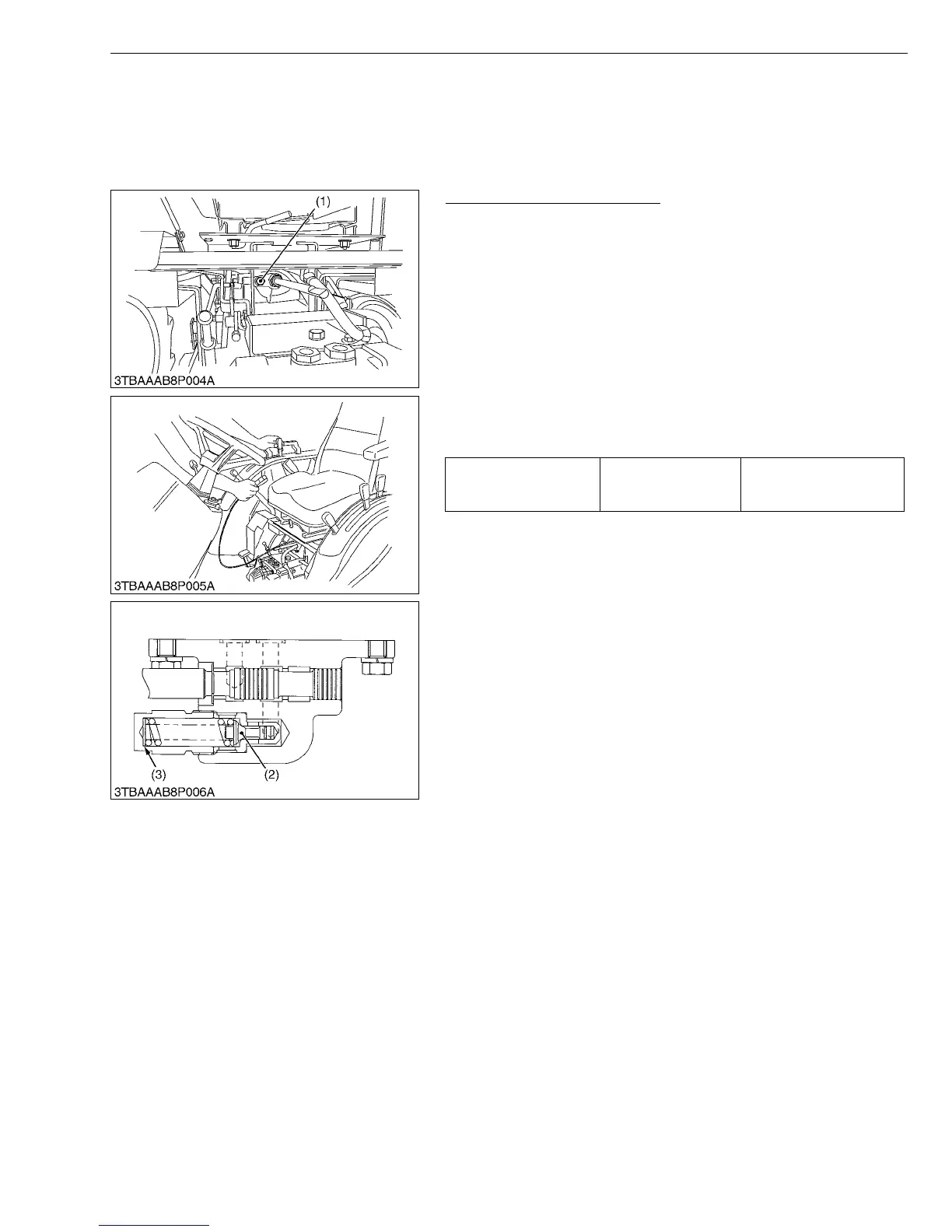
[1] CHECKING AND ADJUSTING
Relief Valve Setting Pressure
1. Remove the seat under cover.
2. Remove the plug (1) from front of hydraulic cylinder body.
3. Install the adaptor 58. Then connect the cable and pressure
gauge to adaptor 58.
4. Remove the feedback rod lock nut and spring.
5. Start the engine and set at maximum speed.
6. Move the hydraulic control lever all way up to operate the relief
valve and read the gauge.
7. If the pressure is not factory specifications, remove the hydraulic
cylinder assembly (refer to 1-S5 to 1-S7) and adjust relief valve
(2) with the adjusting shims (3).
8. Reinstall the hydraulic cylinder assembly. After checking the
pressure, reinstall the spring and feedback rod lock nut.
Condition
• Engine speed .......... Maximum
• Oil temperature ....... 45 to 55 °C
113 to 131 °F
(Reference)
• Thickness of shims (3): 0.1 mm (0.0039 in.), 0.2 mm (0.0079 in.)
W1016613
Relief valve setting
pressure
Factory spec.
13.2 to 14.2 MPa
135 to 145 kgf/cm
2
1920 to 2064 psi
(1) Plug
(2) Relief Valve
(3) Shim
 Loading...


