1 ENGINE
82410· 82710·
82910 WSM, 12271
0.145 to 0.185 mm
0.0057 to 0.0073 in.
Factory spec.Valve clearance
Valve
arrangement
IN.
EX.
Adjustable
cylinder
location of piston
3cyd.
4cyd.
3 cyd.
4cyd.
1st i:l
1::1
i:l
i:l
When No. 1 piston is
2nd
i:l i:l
compression top dead
center
3rd
i:l
1::1
4th
-
1::1
-
1st
When
No.1
piston is
2nd
i:l
i:l
overlap position
3rd
i:l i:l
4th
-
-
i:l
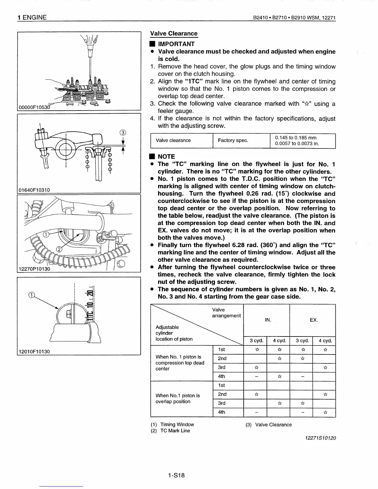
Valve Clearance
• IMPORTANT
• Valve clearance
must
be
checked
and
adjusted
when
engine
is cold.
1.
Remove the head cover, the glow plugs and the timing window
cover
on
the clutch housing.
2.
Align the
"1TC"
mark line on the flywheel and center of timing
window
so
that the No. 1 piston comes to the compression or
overlap top dead center.
3.
Check the following valve clearance marked with
"i::?"
using a
feeler gauge.
4.
If
the clearance
is
not within the factory specifications, adjust
with the adjusting screw.
• NOTE
• The
"TC"
marking
line
on
the
flywheel
is
just
for
No. 1
cylinder. There
is
no
"TC"
marking
for
the
other
cylinders.
•
No.1
piston
comes
to
the
T.O.C.
position
when
the
"TC"
marking
is aligned
with
center
of
timing
window
on
clutch-
housing.
Turn
the
flywheel
0.26 rad. (15°)
clockwise
and
counterclockwise
to
see
if
the
piston
is
at
the
compression
top
dead center
or
the
overlap
position.
Now
referring
to
the table below,
readjust
the
valve
clearance. (The
piston
is
at
the
compression
top
dead
center
when
both
the IN.
and
EX.
valves
do
not
move;
it
is
at
the
overlap
position
when
both
the
valves move.)
• Finally
turn
the
flywheel
6.28 rad. (360°) and
align
the
"TC"
marking
line and
the
center
of
timing
window.
Adjust
all
the
other valve clearance
as
required.
•
After
turning
the
flywheel
counterclockwise
twice
or
three
times, recheck
the
valve clearance,
firmly
tighten
the
lock
nut
of
the
adjusting
screw.
• The sequence
of
cylinder
numbers
is
given
as
No.1,
No.2,
No.3
and
No.4
starting
from
the
gear
case side.
-JI
II
~i
-It
"
::---.-81
'-"
II
I
I
I
I
I
00000F1053
01640F10310
12010F10130
(1) Timing Window
(2)
TC Mark Line
(3)
Valve Clearance
12271510120
1-818
 Loading...


