82410 • 82710 • 82910 WSM, 12271
3 TRANSMISSION
Spring holder mounting
39.2 to
44.1
N·m
4.0 to 4.5 kgf·m
screw
28.9 to 32.5 ft-Ibs
Tightening torque
62.8 to 72.6
N·m
HST and center frame
mounting screw and nut
6.4 to 7.4 kgf·m
46.3 to 53.5 ft-Ibs
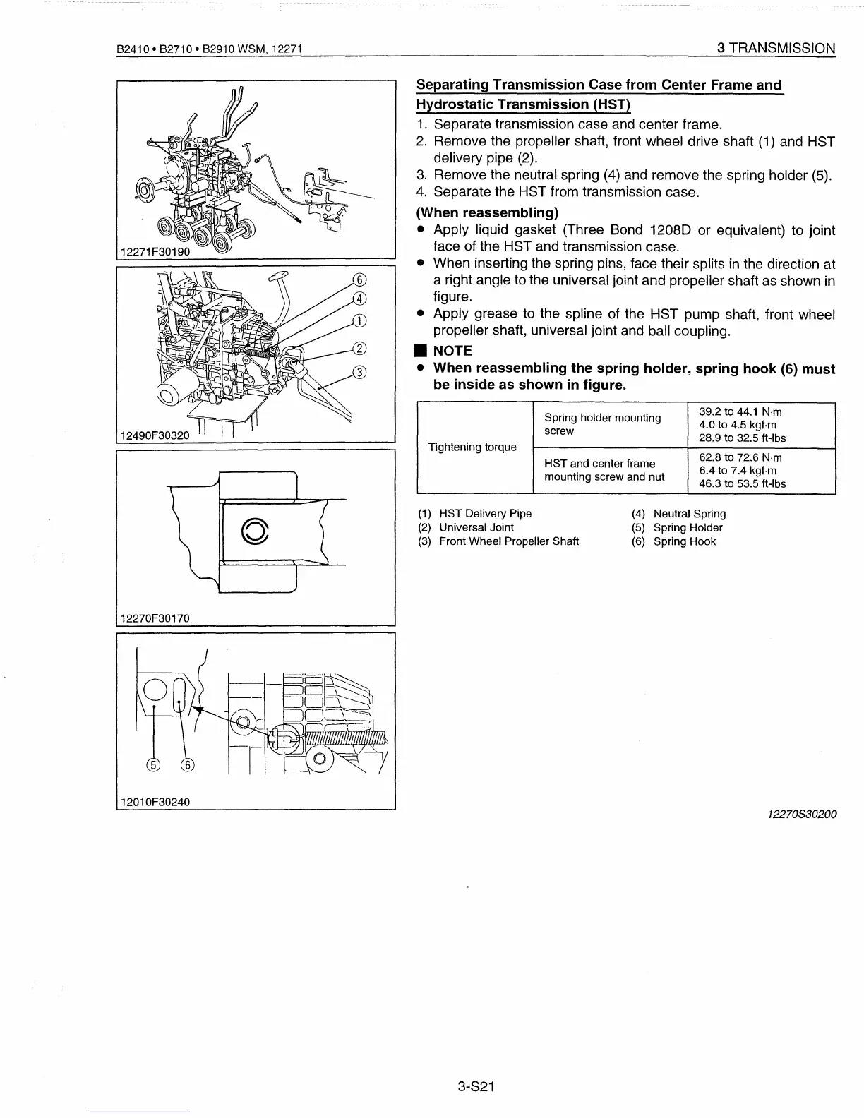
Separating Transmission Case from Center Frame and
Hydrostatic Transmission (HST)
1.
Separate transmission case and center frame.
2.
Remove the propeller shaft, front wheel drive shaft
(1)
and HST
delivery pipe
(2).
3.
Remove the neutral spring
(4)
and remove the spring holder
(5).
4.
Separate the HST from transmission case.
(When reassembling)
• Apply liquid gasket (Three Bond 1208D or equivalent) to joint
face of the HST and transmission case.
• When inserting the spring pins, face their splits
in
the direction at
a right angle to the universal joint and propeller shaft as shown
in
figure.
• Apply grease to the spline of the HST pump shaft, front wheel
propeller shaft, universal joint and ball coupling.
• NOTE
• When reassembling the spring holder, spring hook (6) must
be inside as shown
in
figure.
(4)
Neutral Spring
(5)
Spring Holder
(6)
Spring Hook
(1)
HST Delivery Pipe
(2)
Universal Joint
(3)
Front Wheel Propeller Shaft
12270F30170
12010F30240
12270830200
3-S21
 Loading...


