8 HYDRAULIC SYSTEM
82410·
82710·
82910 WSM,
12271
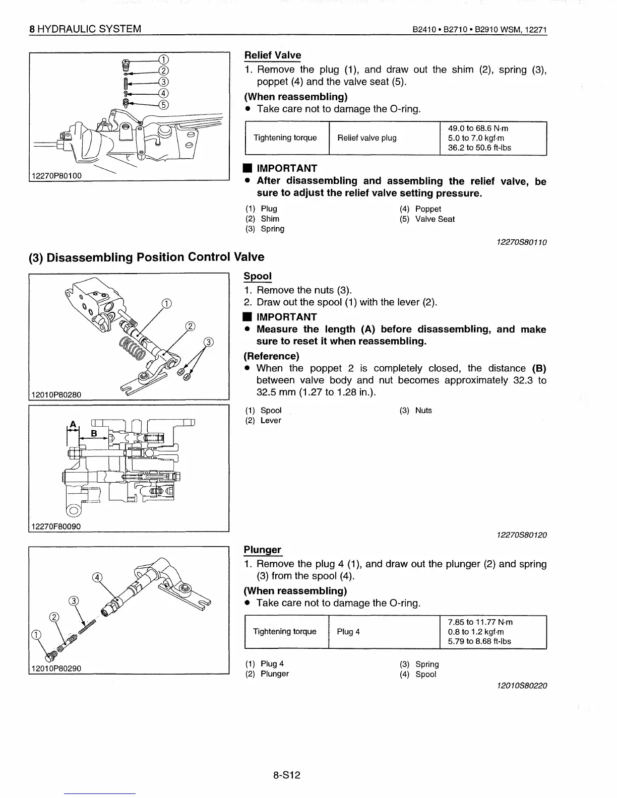
Relief Valve
1.
Remove the plug (1), and draw out the shim (2), spring (3),
poppet (4) and the
valve seat (5).
(When reassembling)
• Take care not to damage the O-ring.
49.0 to 68.6
N·m
Tightening torque
Relief valve plug 5.0 to 7.0 kgf·m
36.2 to 50.6 ft-Ibs
• IMPORTANT
• After disassembling and assembling the relief valve, be
sure to adjust the relief valve setting pressure.
(1)
Plug
(4)
Poppet
(2)
Shim (5) Valve Seat
(3)
Spring
12270880110
(3) Nuts
2
12010P80280
(3) Disassembling Position Control Valve
Spool
1.
Remove the nuts (3).
2. Draw out the spool (1) with the lever (2) .
• IMPORTANT
• Measure the length (A) before disassembling, and make
sure to reset it when reassembling.
(Reference)
• When the poppet 2
is
completely closed, the distance (B)
between valve body and nut becomes approximately 32.3 to
32.5 mm (1.27
to
1.28 in.).
(1)
Spool
(2)
Lever
12270F80090
12270880120
7.85 to 11.77 N·m
Tightening torque
Plug 4 0.8 to 1.2 kgf·m
5.79 to 8.68 ft-Ibs
Plunger
1.
Remove the plug 4 (1), and draw out the plunger (2) and spring
(3) from the spool (4).
(When reassembling)
• Take care not
to
damage the O-ring.
12010P80290
(1)
Plug 4
(2)
Plunger
(3)
Spring
(4)
Spool
12010880220
8-S12
 Loading...


