6 FRONT AXLE
12010F60060
B2410 •
B271
0 •
B291
0 WSM,
12271
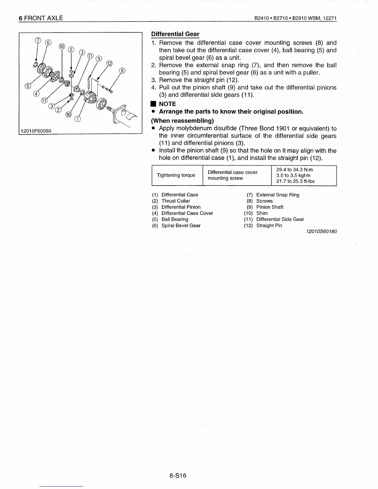
Differential Gear
1.
Remove the differential case cover mounting screws
(8)
and
then take out the differential case cover
(4),
ball bearing
(5)
and
spiral bevel gear (6)
as
a unit.
2.
Remove the external snap ring (7),
and
then remove the ball
bearing
(5)
and spiral bevel gear
(6)
as
a unit with a puller.
3.
Remove the straight pin (12).
4.
Pull out the pinion shaft
(9)
and take out the differential pinions
(3)
and differential side gears (11).
• NOTE
• Arrange the parts to know their original position.
(When reassembling)
• Apply molybdenum disulfide (Three Bond
1901
or equivalent) to
the inner circumferential surface of the differential side gears
(11)
and differential pinions (3).
• Install the pinion shaft
(9)
so that the hole
on
it may align with the
hole
on
differential case (1), and install the straight
pin
(12).
Differential case cover
29.4 to 34.3
N·m
Tightening torque
mounting screw
3.0 to 3.5 kgf·m
21.7 to 25.3 ft-Ibs
(1)
Differential Case
(2)
Thrust Collar
(3)
Differential Pinion
(4)
Differential Case Cover
(5)
Ball Bearing
(6)
Spiral Bevel Gear
6-816
(7)
External Snap Ring
(8)
Screws
(9)
Pinion Shaft
(10) Shim
(11) Differential Side Gear
(12) Straight
Pin
120
10S60
180
 Loading...


