82410 • 82710 • 82910
WSM,
12271
(2)
Glow
Plug
9 ELECTRICAL SYSTEM
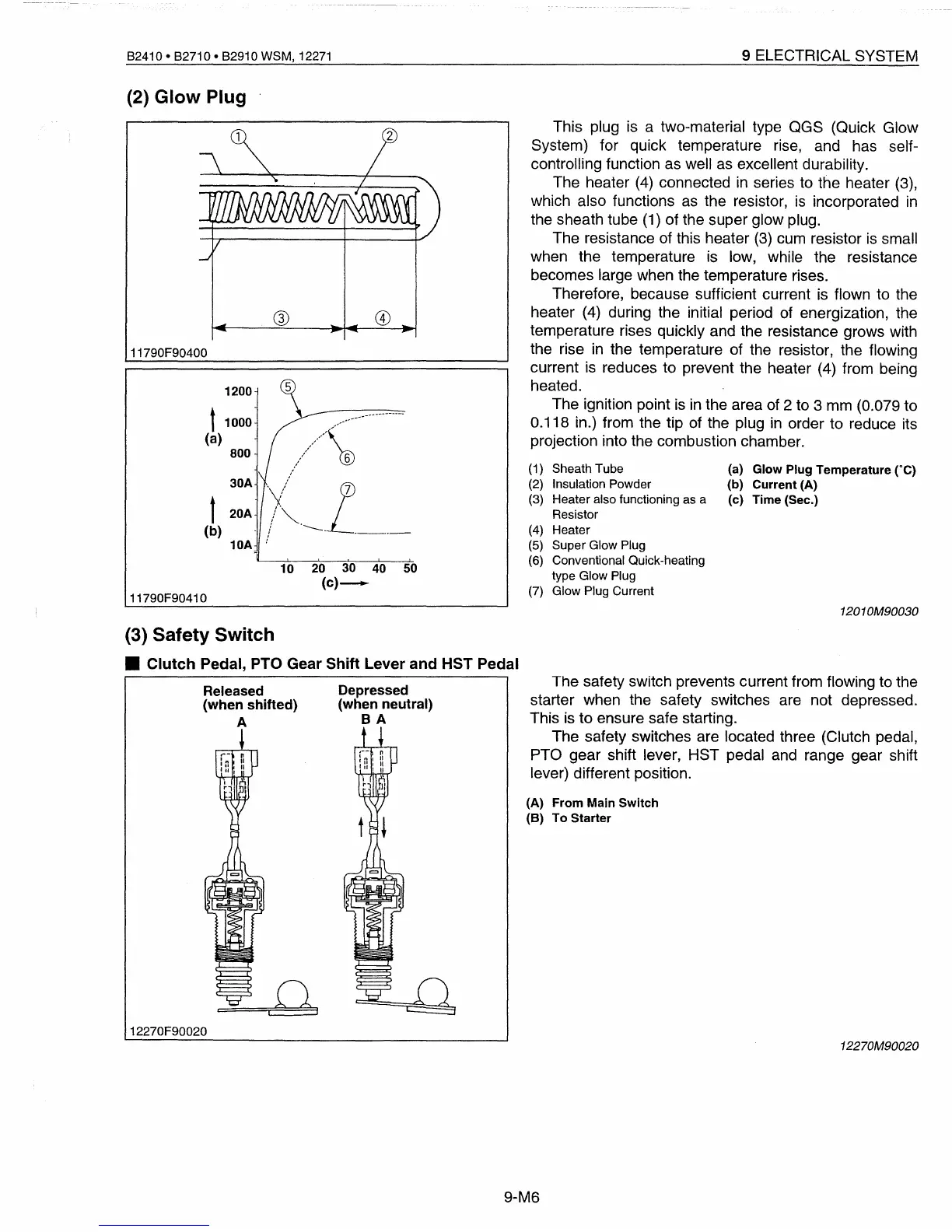
This plug
is
a two-material type QGS (Quick Glow
System) for quick temperature rise, and has self-
controlling function as well
as
excellent durability.
The heater
(4)
connected
in
series to the heater (3),
which also functions
as
the resistor,
is
incorporated
in
the sheath tube
(1)
of the super glow plug.
The resistance of this heater
(3)
cum resistor
is
small
when the temperature is low, while the resistance
becomes large when the temperature rises.
Therefore, because sufficient current
is
flown to the
heater
(4)
during the initial period of energization, the
temperature rises qUickly and the resistance grows with
the rise
in
the temperature of the resistor, the flowing
current
is
reduces to prevent the heater (4) from being
heated.
The ignition point
is
in
the area of 2 to 3 mm (0.079 to
0.118 in.) from the tip of the plug
in
order to reduce its
projection into the combustion chamber.
®
11790F90400
1200
t1000
(a)
800
30A
t 20A
(b)
10A
10 20 30 40 50
(c)-
11790F90410
(1) Sheath Tube
(2) Insulation Powder
(3)
Heater also functioning as a
Resistor
(4) Heater
(5)
Super Glow Plug
(6) Conventional Quick-heating
type Glow Plug
(7) Glow Plug Current
(a)
Glow
Plug
Temperature
eC)
(b)
Current
(A)
(c)
Time
(Sec.)
1201OM90030
(3)
Safety
Switch
•
Clutch
Pedal, PTO Gear Shift Lever
and
HST Pedal
Released
(when
shifted)
A
o
i i
12270F90020
Depressed
(when neutral)
BA
The safety switch prevents current from flowing to the
starter when the safety switches are not depressed.
This
is
to ensure safe starting.
The safety switches are located three (Clutch pedal,
PTa
gear shift lever, HST pedal and range gear shift
lever) different position.
(A)
From
Main
Switch
(B)
To
Starter
12270M90020
9-M6
 Loading...


