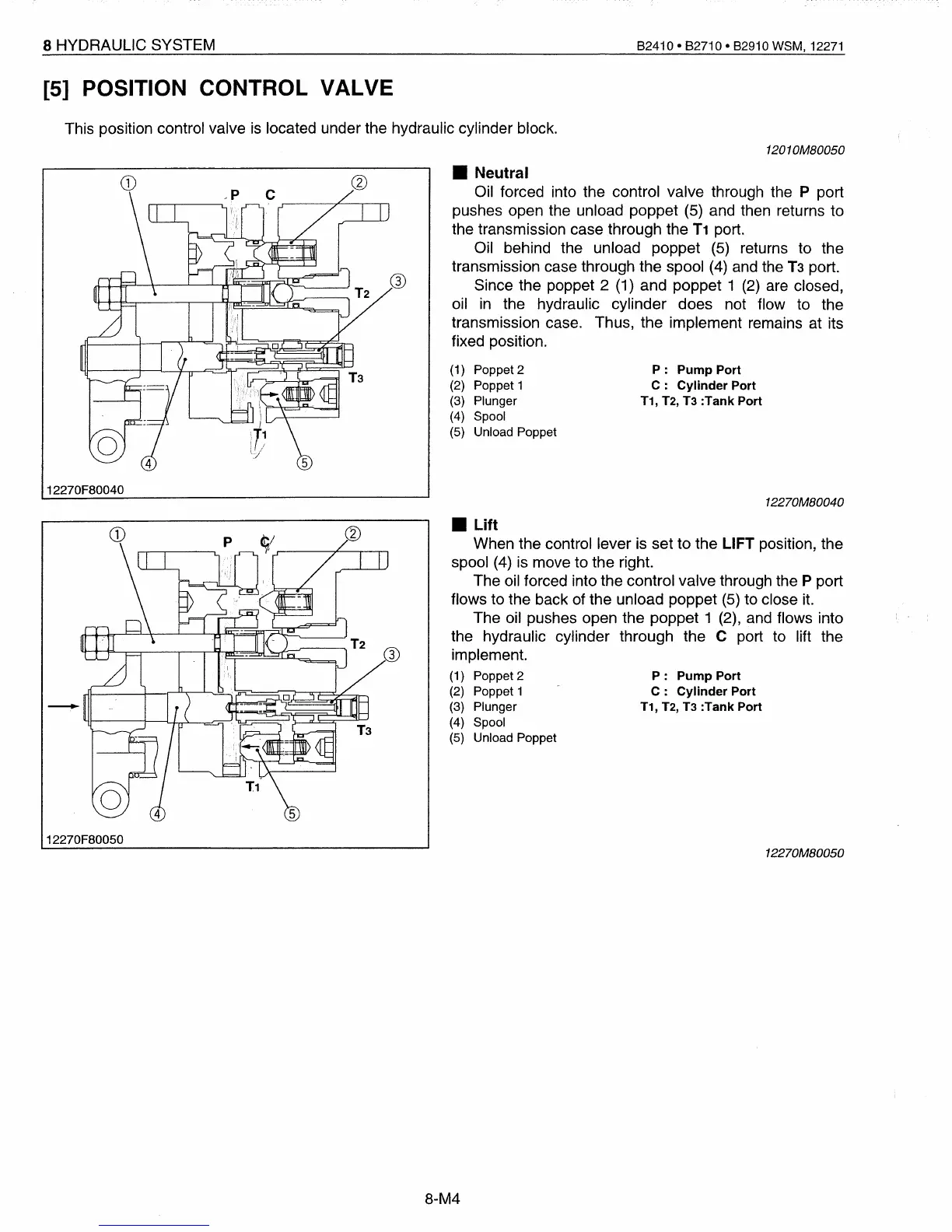
• Neutral
Oil forced into the control valve through the P port
pushes open the unload poppet (5) and then returns to
the transmission case through the
T1
port.
Oil behind the unload poppet (5) returns to the
transmission case through the spool (4) and the
T3
port.
Since the poppet 2 (1) and poppet 1 (2) are closed,
oil
in
the hydraulic cylinder does not flow to the
transmission case. Thus, the implement remains at its
fixed position.
8 HYDRAULIC SYSTEM
[5]
POSITION CONTROL VALVE
This position control valve
is
located under the hydraulic cylinder block.
(1) Poppet 2
(2) Poppet 1
(3) Plunger
(4) Spool
(5) Unload Poppet
12270F80040
82410·
82710·
82910 WSM, 12271
1201OMB0050
P:
Pump
Port
C:
Cylinder Port
T1,
T2,
T3
:Tank Port
12270MB0040
P:
Pump
Port
C:
Cylinder Port
T1,
T2,
T3
:Tank Port
12270F80050
• Lift
When the control lever is set to the LIFT position, the
spool (4) is move to the right.
The oil forced into the control valve through the P port
flows to the back of the unload poppet (5) to close it.
The oil pushes open the poppet 1 (2), and flows into
the hydraulic cylinder through the C port to lift the
implement.
(1) Poppet 2
(2) Poppet 1
(3) Plunger
(4) Spool
(5) Unload Poppet
12270MB0050
8-M4
 Loading...


