8 HYDRAULIC
SYSTEM
82410· 82710·
82910 WSM,
12271
C
B
P:
Pump
Port
C:
Cylinder
Port
S:
Slit
T1,
T3
:Tank
Port
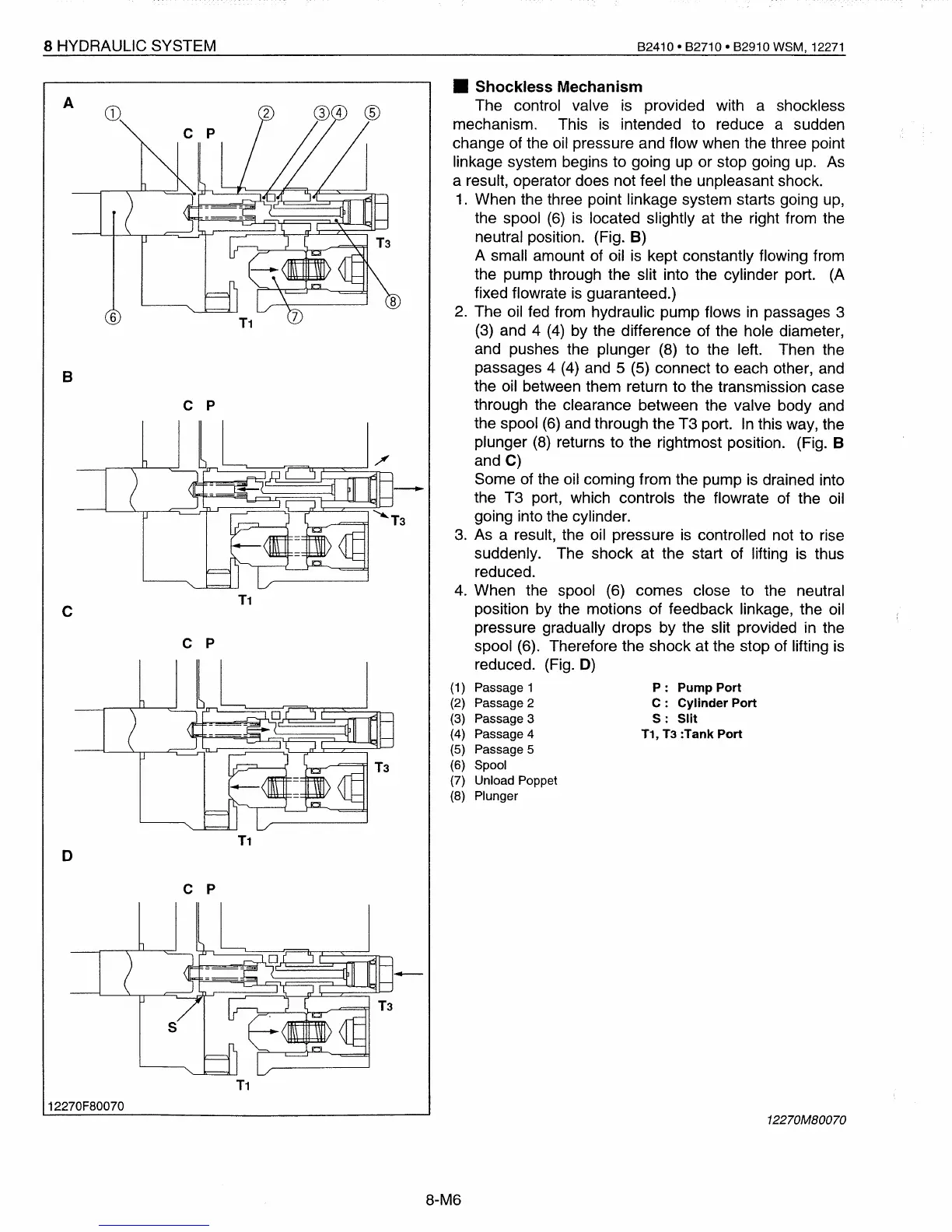
• Shockless Mechanism
The control valve
is
provided with a shockless
mechanism. This
is
intended to reduce a sudden
change of the
oil
pressure and flow when the three point
linkage system begins to going
up
or stop going
up.
As
a result, operator does not feel the unpleasant shock.
1.
When the three point linkage system starts going
up,
the spool
(6)
is
located slightly at the right from the
neutral position. (Fig. B)
A small amount of oil
is
kept constantly flowing from
the pump through the slit into the cylinder port. (A
fixed flowrate
is
guaranteed.)
2.
The oil
fed
from hydraulic pump flows
in
passages 3
(3)
and 4
(4)
by the difference of the hole diameter,
and pushes the plunger
(8)
to the left. Then the
passages 4
(4)
and 5
(5)
connect to each other, and
the oil between them return to the transmission case
through the clearance between the valve body and
the spool
(6)
and through the T3 port.
In
this way, the
plunger
(8)
returns to the rightmost position. (Fig. B
and
C)
Some of the oil coming from the pump
is
drained into
the T3 port, which controls the flowrate
of
the oil
going into the cylinder.
3.
As
a result, the oil pressure
is
controlled not to rise
suddenly. The shock at the start
of
lifting
is
thus
reduced.
4.
When the spool
(6)
comes close to the neutral
position
by
the motions of feedback linkage, the oil
pressure gradually drops by the slit provided
in
the
spool (6). Therefore the shock at the stop of lifting
is
reduced. (Fig.
D)
(1) Passage 1
(2) Passage 2
(3) Passage 3
(4) Passage 4
(5) Passage 5
(6) Spool
(7) Unload Poppet
(8) Plunger
T1
A
c p
c p
D
T1
c p
T1
12270F80070
12270MB0070
8-M6
 Loading...


