82410
• 82710 • 82910 WSM, 12271
[2] ENGINE BODY
CHECKING AND ADJUSTING
1 ENGINE
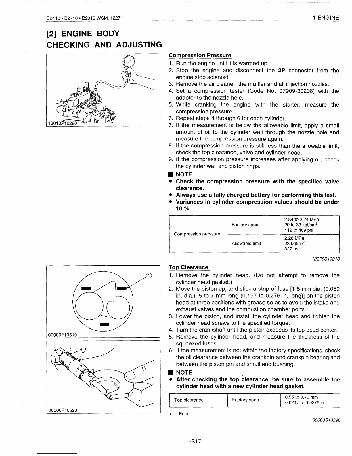
Compression Pressure
1.
Run the engine until
it
is
warmed up.
2.
Stop the engine and disconnect the 2P connector from the
engine stop solenoid.
3.
Remove the air cleaner, the muffler and all injection nozzles.
4.
Set a compression tester (Code No. 07909-30208) with the
adaptor to the nozzle hole.
5.
While cranking the engine with the starter, measure the
compression pressure.
6.
Repeat steps 4 through 6 for each cylinder.
7.
If
the measurement
is
below the allowable limit, apply a small
amount of oil to the cylinder wall through the nozzle hole and
measure the compression pressure again.
8.
If
the compression pressure
is
still less than the allowable limit,
check the top clearance, valve and cylinder head.
9.
If the compression pressure increases after applying oil, check
the cylinder wall and piston rings.
• NOTE
• Check the compression pressure with the specified valve
clearance.
• Always use a fully charged battery for performing this test.
• Variances
in
cylinder compression values should be under
10
0
/0.
2.84 to 3.24 MPa
Factory spec.
29 to 33 kgf/cm
2
Compression pressure
412 to 469 psi
2.26 MPa
Allowable limit
23 kgf/cm
2
327 psi
12270810210
Top Clearance
1.
Remove the cylinder head. (Do not attempt to remove the
cylinder head gasket.)
2. Move the piston
up,
and stick a strip of fuse [1.5
mm
dia. (0.059
in. dia.), 5 to 7 mm long (0.197 to 0.276
in.
long)]
on
the piston
head at three positions with grease so as to
avoid the intake and
exhaust valves and the combustion chamber ports.
3.
Lower the piston, and install the cylinder head and tighten the
cylinder head screws to the specified torque.
4.
Turn the crankshaft until the piston exceeds its top dead center.
5.
Remove the cylinder head, and measure the thickness
of
the
squeezed fuses.
6.
If the measurement
is
not within the factory specifications, check
the oil clearance between the crankpin and crankpin bearing and
between the piston pin and small end bushing.
• NOTE
• After checking the top clearance, be sure to assemble the
cylinder head with a new cylinder head gasket.
00000F10510
00000F10520
Top clearance
(1) Fuse
1-817
Factory spec.
0.55 to 0.70
mm
0.0217 to 0.0276
in.
00000810390
 Loading...


