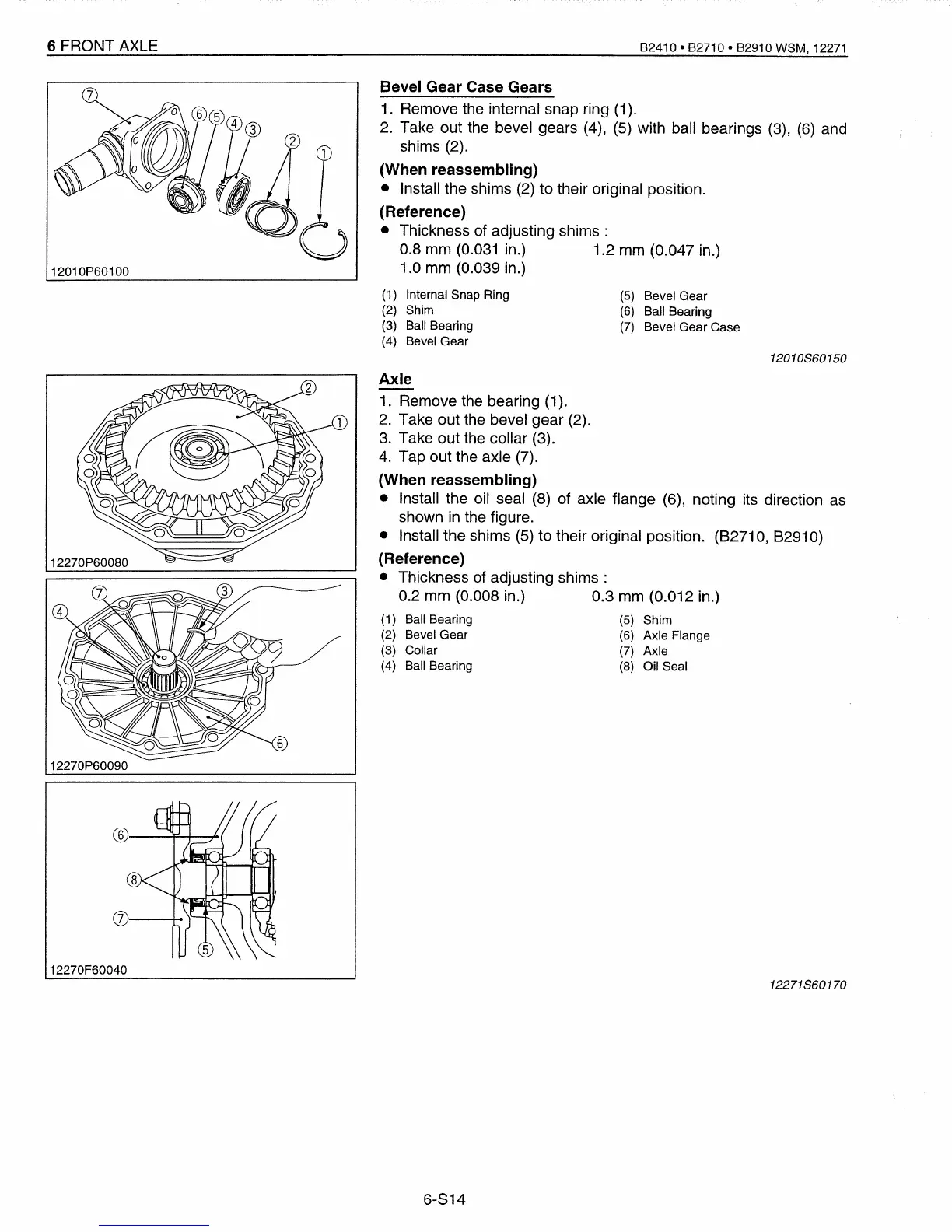
(5) Bevel Gear
(6)
Ball Bearing
(7)
Bevel Gear Case
6 FRONT AXLE
12010P60100
12270P60080
12270P60090
12270F60040
B2410 • B2710 • B2910
WSM,
12271
Bevel Gear Case Gears
1. Remove the internal snap ring (1).
2. Take out the bevel gears (4), (5) with ball bearings (3),
(6)
and
shims (2).
(When reassembling)
• Install the shims (2) to their original position.
(Reference)
• Thickness of adjusting
shims:
0.8 mm (0.031 in.)
1.2
mm (0.047 in.)
1.0 mm (0.039 in.)
(1) Internal Snap Ring
(2)
Shim
(3) Ball Bearing
(4) Bevel Gear
12010860150
Axle
1. Remove the bearing (1).
2.
Take out the bevel gear (2).
3.
Take out the collar (3).
4. Tap out the axle (7).
(When reassembling)
• Install the oil seal (8) of axle flange (6), noting its direction as
shown in the figure.
• Install the shims (5)
to
their original position.
(82710,
82910)
(Reference)
• Thickness of adjusting
shims:
0.2 mm (0.008 in.)
0.3
mm (0.012 in.)
(1)
Ball Bearing
(5)
Shim
(2)
Bevel Gear
(6)
Axle Flange
(3)
Collar
(7)
Axle
(4)
Ball Bearing
(8)
Oil Seal
12271860170
6-814
 Loading...


