1-M1
B7800HSD (SUPPLEMENT), WSM
HYDRAULIC SYSTEM
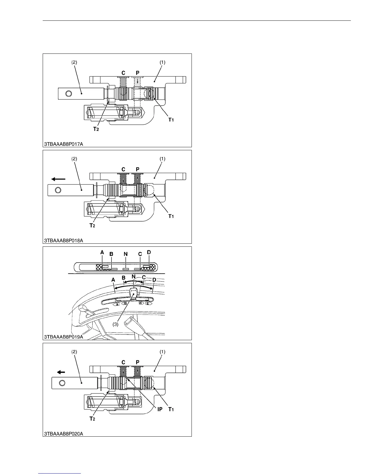
1. CONTROL VALVE (QUARTER INCHING VALVE)
This implement control valve (quarter inching valve) is located under the hydraulic cylinder block.
Q Neutral
Oil forced into the control valve (1) through P port and
returns to the transmission case through T1 port.
Also, C port is closed by spool (2), oil in the hydraulic
cylinder does not flow to the transmission case.
Thus, the implement remains at its fixed position.
W1012665
Q Up
When the control lever is set to the “Up” position, the
spool (2) is moved to the left.
The oil forced into the control valve (1) through P port
flows to C port.
The oil pushes and flows into the hydraulic cylinder
through the C port to lift the implement.
W1012786
Q Slow Up (Quarter Inching Control)
When the hydraulic control lever (3) is set to “SLOW
UP” position (C), the spool (2) is slightly moved to the left.
The oil forced into the control valve (1) from P port
flows to C port in response to the movement of the
hydraulic control lever (3).
Since the spool (2) is two stepped land spool, the oil
forced in the oil passage (IP) between the spool (2) and
the control valve body is throttled, and less quantity of
hydraulic oil flows from P port, through this oil passage
(IP), to C port.
At this time, the hydraulic control lever (3) enables to
control the valve easily in increments of approximately 1/
4 inches “SLOW UP” at the lower link end.
W1019771
(1) Control Valve
(2) Spool
P: Pump Port
C: Cylinder Port
T
1:Tank Port 1
T
2:Tank Port 2
(1) Control Valve
(2) Spool
P: Pump Port
C: Cylinder Port
T
1:Tank Port 1
T
2:Tank Port 2
(1) Control Valve
(2) Spool
(3) Hydraulic Control Lever
P: Pump Port
C: Cylinder Port
T
1: Tank Port 1
T
2: Tank Port 2
A: Down
B: SLOW DOWN
C: SLOW UP
D: UP
N: NEUTRAL
IP: Oil Passage (Pump Side)
 Loading...


