82410 • 82710 • 82910
WSM,
12271
9 ELECTRICAL SYSTEM
Connector
Voltage
1.
Measure the voltage with a voltmeter across the connector 30
terminal and chassis.
2.
If the voltage differs from the battery voltage
(11
to 14
V),
the
wiring harness is faulty.
11900F90010
Voltage
Connector 30
terminal - chassis
Approx. battery voltage
12010890060
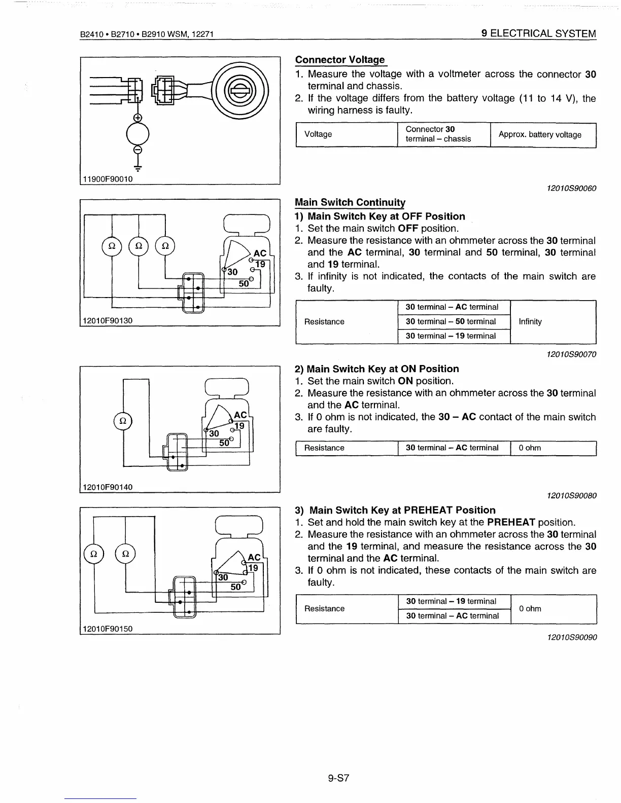
12010F90130
Main
Switch
Continuity
1)
Main
Switch
Key
at
OFF
Position
1. Set the main switch OFF position.
2.
Measure the resistance with an ohmmeter across the 30 terminal
and the
AC
terminal, 30 terminal and 50 terminal, 30 terminal
and 19 terminal.
3.
If infinity is not indicated, the contacts of the main switch are
faulty.
30 terminal - AC terminal
Resistance
30 terminal - 50 terminal Infinity
30 terminal -
19
terminal
12010890070
2)
Main
Switch
Key
at
ON
Position
1.
Set the main switch ON position.
2.
Measure the resistance with an ohmmeter across the 30 terminal
and the AC terminal.
3.
If 0 ohm is not indicated, the 30 -
AC
contact of the main switch
are faulty.
12010F90140
Resistance
30 terminal - AC terminal
Oohm
12010890080
12010F90150
3)
Main
Switch
Key
at
PREHEAT
Position
1. Set and hold the main switch key at the PREHEAT position.
2.
Measure the resistance with an ohmmeter across the 30 terminal
and the 19 terminal, and measure the resistance across the 30
terminal and the
AC
terminal.
3.
If 0 ohm
is
not indicated, these contacts of the main switch are
faulty.
30
terminal-19
terminal
Resistance
oohm
30 terminal - AC terminal
12010890090
9-S7
 Loading...


