EasyManuals Logo

Kubota B2910 User Manual

Kubota B2910
426 pages
To Next Page IconTo Next Page
To Previous Page IconTo Previous Page
Page #405 background imageLoading...
Page #405 background image
1-M4
B7800HSD (SUPPLEMENT), WSM
HYDRAULIC SYSTEM
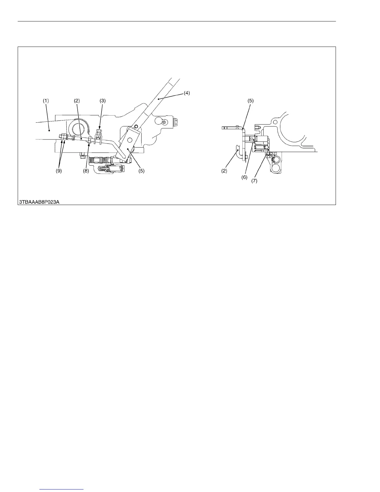
3. FEEDBACK LINKAGE
When the hydraulic control lever (4) moved to rearward to lift the implement, the spool of the control valve is pulled
out to form a raising circuit by the motions of feedback arm (5), control lever shaft (6) and control lever arm (7). And
after the lift arm (1) moves upward, the spool is pushed in and returned to form a neutral circuit by the motions of
interlocker (3), lock nut (9), feedback rod (2), feedback arm (5), control lever shaft (6) and control lever arm (7).
(1) Lift Arm RH
(2) Feedback Rod
(3) Interlocker
(4) Hydraulic Control Lever
(5) Feedback Arm
(6) Control Lever Shaft
(7) Control Lever Arm
(8) Feedback Pin
(9) Lock Nut
KiSC issued 09, 2007 A

Table of Contents

Questions and Answers:

Question and Answer IconNeed help?

Do you have a question about the Kubota B2910 and is the answer not in the manual?

Kubota B2910 Specifications

General IconGeneral
Fuel TypeDiesel
Transmission TypeHydrostatic
Hydraulic SystemOpen center
3-Point HitchCategory I
Lift Capacity1, 323 lbs (600 kg)
Drive4WD
Engine TypeDiesel, 4-cycle, liquid-cooled
Horsepower30 hp
Number of GearsInfinite (3 ranges)
Wheelbase63 inches
PTO Horsepower22 hp

Related product manuals