2 CLUTCH
[2]
LINKAGE MECHANISM
12490F20010
B2410·
B2710·
B2910 WSM, 12271
®}
@@
®
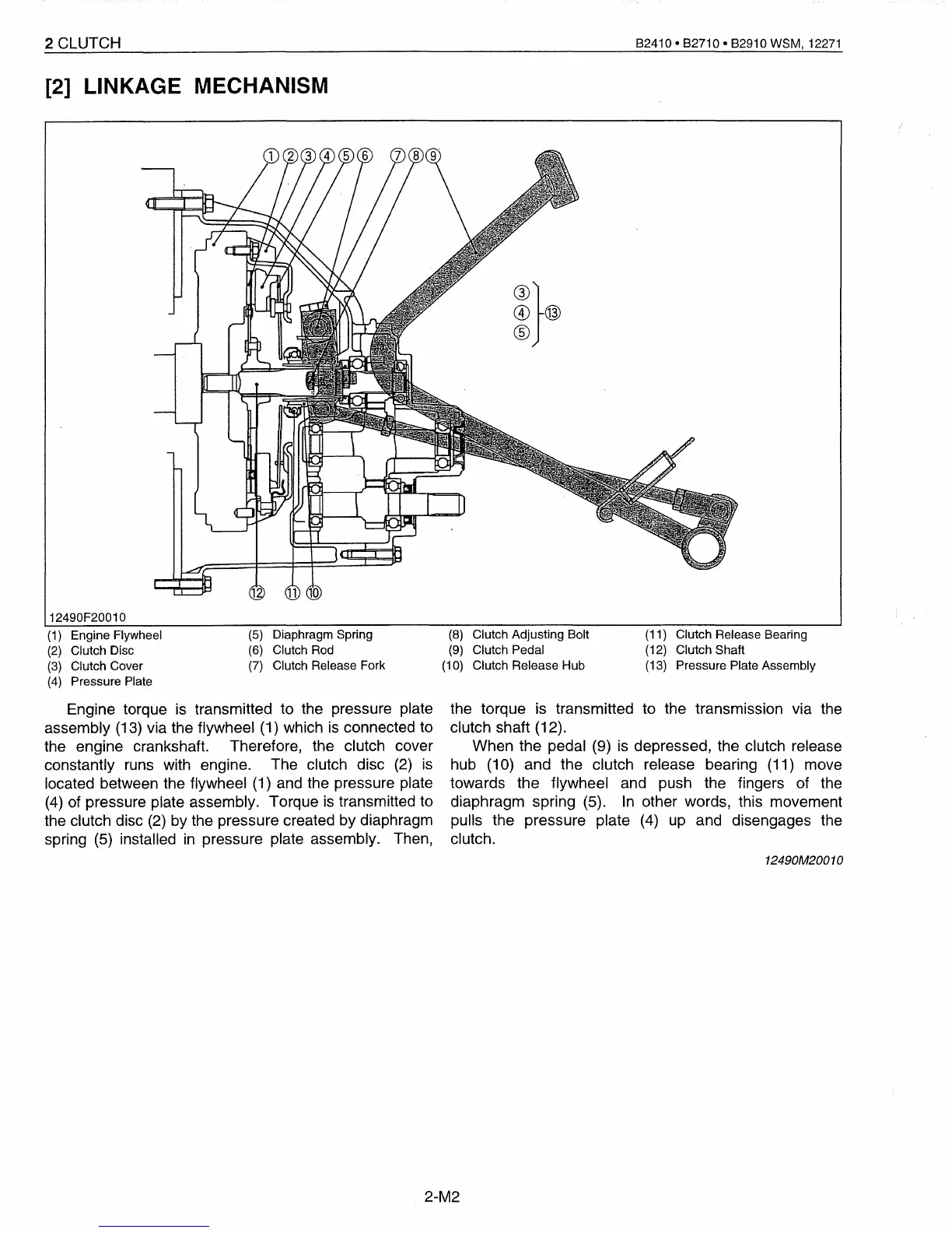
(5) Diaphragm Spring
(6) Clutch
Rod
(7)
Clutch Release Fork
the torque
is
transmitted to the transmission via the
clutch shaft (12).
When the pedal (9)
is
depressed, the clutch release
hub (10) and the clutch release bearing (11) move
towards the flywheel and push the fingers of the
diaphragm spring (5).
In
other words, this movement
pulls the pressure plate
(4)
up
and disengages the
clutch.
(1)
Engine Flywheel
(2)
Clutch Disc
(3)
Clutch Cover
(4)
Pressure Plate
Engine torque
is
transmitted to the pressure plate
assembly (13) via the flywheel (1) which
is
connected to
the engine crankshaft. Therefore, the clutch cover
constantly runs with engine. The clutch disc
(2)
is
located between the flywheel (1) and the pressure plate
(4)
of pressure plate assembly. Torque
is
transmitted to
the clutch disc
(2)
by the pressure created by diaphragm
spring (5) installed
in
pressure plate assembly. Then,
(8)
Clutch Adjusting Bolt
(9)
Clutch Pedal
(10) Clutch Release Hub
(11) Clutch Release Bearing
(12) Clutch Shaft
(13) Pressure Plate Assembly
12490M20010
2-M2
 Loading...


