1 ENGINE
B2410 •
B271
0 • B2910 WSM, 12271
(4)
Crankshaft
~
2010P10390
Flywheel
1.
Fit the stopper to the flywheel.
2. Remove the flywheel screws and then remove the flywheel.
(When
reassembling)
• Fit the flywheel giving care to the position of the knock pin.
• Apply engine oil to the threads and the undercut surface of the
flywheel bolt and fit the bolt.
53.9 to 58.8 N·m
Tightening torque Flywheel screw
5.5 to 6.0 kgf·m
39.8 to 43.4 ft-Ibs
12010810410
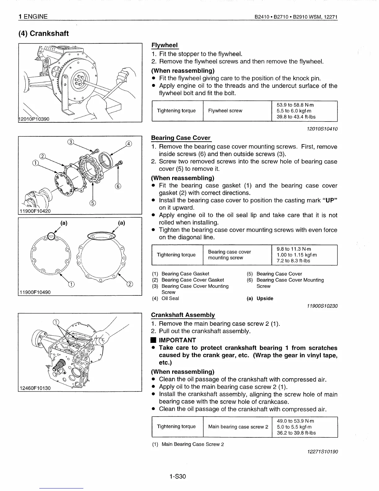
{5}
Bearing Case Cover
{6}
Bearing Case Cover Mounting
Screw
(a) Upside
{1}
Bearing Case Gasket
{2}
Bearing Case Cover Gasket
{3}
Bearing Case Cover Mounting
Screw
{4}
Oil Seal
Bearing case cover
9.8 to 11.3 N·m
Tightening torque 1.00 to 1.15 kgf·m
mounting screw
7.2 to 8.3 ft-Ibs
Bearing Case
Cover
1.
Remove the bearing case cover mounting screws. First, remove
inside screws (6) and then outside screws (3).
2.
Screw two removed screws into the screw hole of bearing case
cover (5) to
remove
it.
(When
reassembling)
• Fit the bearing case gasket (1) and the bearing case cover
gasket (2) with correct directions.
• Install the bearing case
cover to position the casting mark
"UP"
on
it upward.
• Apply engine oil to the oil seal lip and take care that it
is
not
rolled when installing.
• Tighten the bearing case cover mounting screws with
even force
on
the diagonal line.
2
(a)
~
::~\.::..~\
..
~\
\IJ/
..
&,
"Jt\
J)
11900F10420
11900F10490
11900810230
12460F10130
Crankshaft
Assembly
1.
Remove the main bearing case screw 2 (1).
2.
Pull out the crankshaft assembly.
• IMPORTANT
• Take care
to
protect
crankshaft
bearing
1
from
scratches
caused
by
the
crank
gear, etc. (Wrap
the
gear
in
vinyl
tape,
etc.)
(When
reassembling)
• Clean the oil passage of the crankshaft with compressed air.
• Apply oil to the main bearing case screw 2 (1).
• Install the crankshaft assembly, aligning the screw hole of main
bearing case with the screw hole of crankcase.
• Clean the oil passage of the crankshaft with compressed air.
49.0 to 53.9
N·m
Tightening torque
Main bearing case screw 2
5.0 to 5.5 kgf·m
36.2 to 39.8 ft-Ibs
(1)
Main Bearing Case Screw 2
12271810190
1-S30
 Loading...


