B2410 • B2710 •
B291
0 WSM, 12271
DISASSEMBLING AND ASSEMBLING
Disassembling Starter
9 ELECTRICAL SYSTEM
12010F90040
®
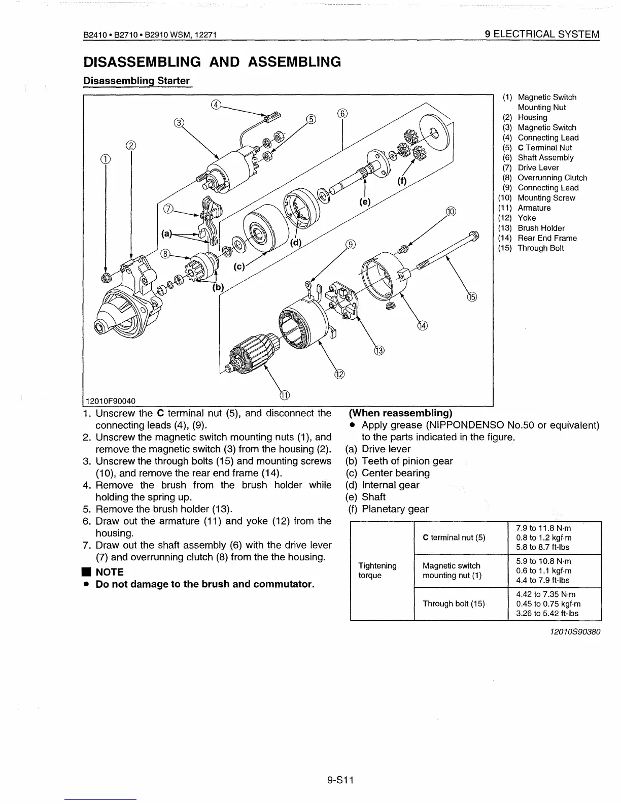
(1)
Magnetic Switch
Mounting Nut
(2)
Housing
(3)
Magnetic Switch
(4)
Connecting Lead
(5)
C Terminal Nut
(6)
Shaft Assembly
(7)
Drive Lever
(8)
Overrunning Clutch
(9)
Connecting Lead
(10)
Mounting Screw
(11)
Armature
(12)
Yoke
(13)
Brush Holder
(14)
Rear End Frame
(15)
Through Bolt
1.
Unscrew the C terminal nut (5), and disconnect the
connecting leads (4), (9).
2.
Unscrew the magnetic switch mounting nuts
(1),
and
remove the magnetic switch
(3)
from the housing
(2).
3.
Unscrew the through bolts (15) and mounting screws
(10), and remove the rear end frame (14).
4.
Remove the brush from the brush holder while
holding the spring up.
5.
Remove the brush holder (13).
6.
Draw out the armature (11) and yoke (12) from the
housing.
7. Draw out the shaft assembly (6) with the drive lever
(7) and overrunning clutch
(8)
from the the housing.
•
NOTE
• Do not damage to the brush and commutator.
(When reassembling)
• Apply grease (NIPPONDENSO No.50 or equivalent)
to the parts indicated
in
the figure.
(a) Drive lever
(b)
Teeth of pinion gear
(c) Center bearing
(d)
Internal gear
(e)
Shaft
(f)
Planetary gear
7.9 to 11.8
N·m
C terminal nut (5)
0.8 to 1.2 kgf·m
5.8 to 8.7 ft-Ibs
Tightening Magnetic switch
5.9 to 10.8 N·m
0.6 to
1.1
kgf·m
torque
mounting nut
(1)
4.4 to 7.9 ft-Ibs
4.42
to
7.35 N·m
Through bolt (15)
0.45
to
0.75 kgf·m
3.26
to
5.42 ft-Ibs
12010890380
9-S11
 Loading...


