82410 • 82710 • 82910 WSM, 12271
DISASSEMBLING AND ASSEMBLING
(1) Cylinder Head and Valves
1 ENGINE
2
12270P10140
Dynamo, Fan Belt and Muffler
1.
Remove the dynamo
(1)
and fan belt (2).
2.
Remove the cooling fan
(3)
and fan pulley.
3.
Remove the air cleaner assembly and stay.
4.
Remove the muffler (5).
(When reassembling)
• Check to see that there are no cracks
on
the belt surface.
• IMPORTANT
• After reassembling the fan belt, be sure to adjust the
fan
belt tension (See page G-22).
(1)
Dynamo
(4)
Air Cleaner
(2)
Fan 8elt
(5)
Muffler
(3)
Cooling Fan
12271810130
Cylinder Head Cover and Injection Pipes
1.
Remove the head cover cap nuts.
2.
Remove the cylinder head cover.
3.
Loosen the screws on the pipe clamps.
4.
Detach the injection pipes.
(When reassembling)
• Check to see if the cylinder head cover gasket
is
not defective.
• Sent compressed air into the pipes to
blowout
dust. Then,
reassemble the pipes
in
the reverse order.
Cylinder head cover cap
6.9 to 8.8 N·m
0.7 to 0.9 kgf·m
nut
5.1
to 6.5 ft-Ibs
Tightening torque
24.5 to 34.3
N·m
Injection pipe retaining nut
2.5 to 3.5 kgf·m
18.1
to 25.3 ft-Ibs
12270810240
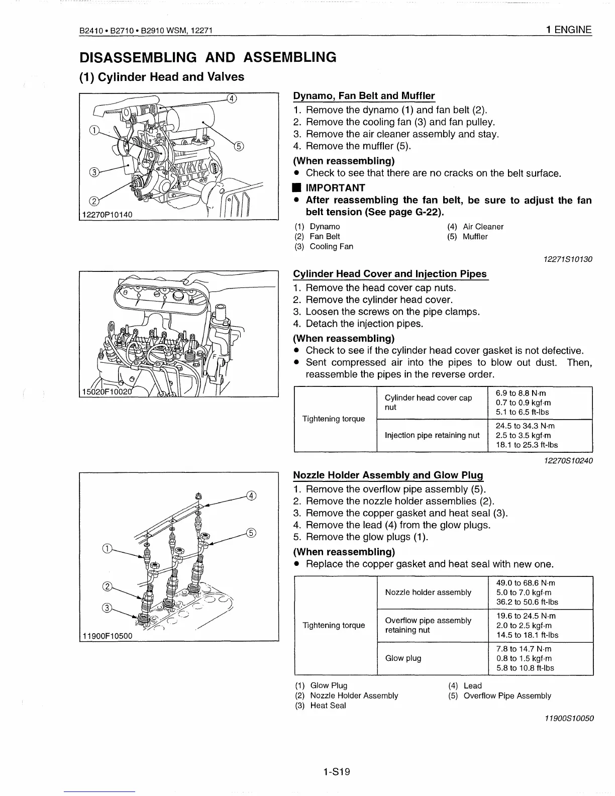
Nozzle Holder Assembly and Glow Plug
1.
Remove the overflow pipe assembly (5).
2.
Remove the nozzle holder assemblies (2).
3.
Remove the copper gasket and heat seal (3).
4.
Remove the lead
(4)
from the glow plugs.
5.
Remove the glow plugs (1).
(When reassembling)
• Replace the copper gasket and heat seal with new one.
49.0 to 68.6
N·m
Nozzle holder assembly
5.0 to 7.0 kgf·m
36.2
to
50.6 ft-Ibs
Overflow pipe assembly
19.6 to 24.5 N·m
lightening
torque
2.0 to 2.5 kgf·m
retaining nut
14.5 to
18.1
ft-Ibs
7.8 to 14.7 N·m
Glow plug
0.8 to 1.5 kgf·m
5.8 to 10.8 ft-Ibs
(1)
Glow Plug
(2)
Nozzle Holder Assembly
(3)
Heat Seal
1-S19
(4)
Lead
(5)
Overflow Pipe Assembly
11900810050
 Loading...


