6 FRONT AXLE
(2) 4 Wheel Drive Model
B241
0 • B2710 •
B291
0 WSM,
12271
12270F60010
(1)
Axle
(7)
Differential Yoke Shaft,
LH
(2)
Axle Flange
(8)
Front Axle Case
(3)
Bevel Gear
(9)
Differential Gear Assembly
(4)
Bevel Gear (10) Differential Pinion Gear
(5)
Bevel Gear Case (11) Pinion Shaft
(6)
Bevel Gear (12) Spiral Bevel Gear
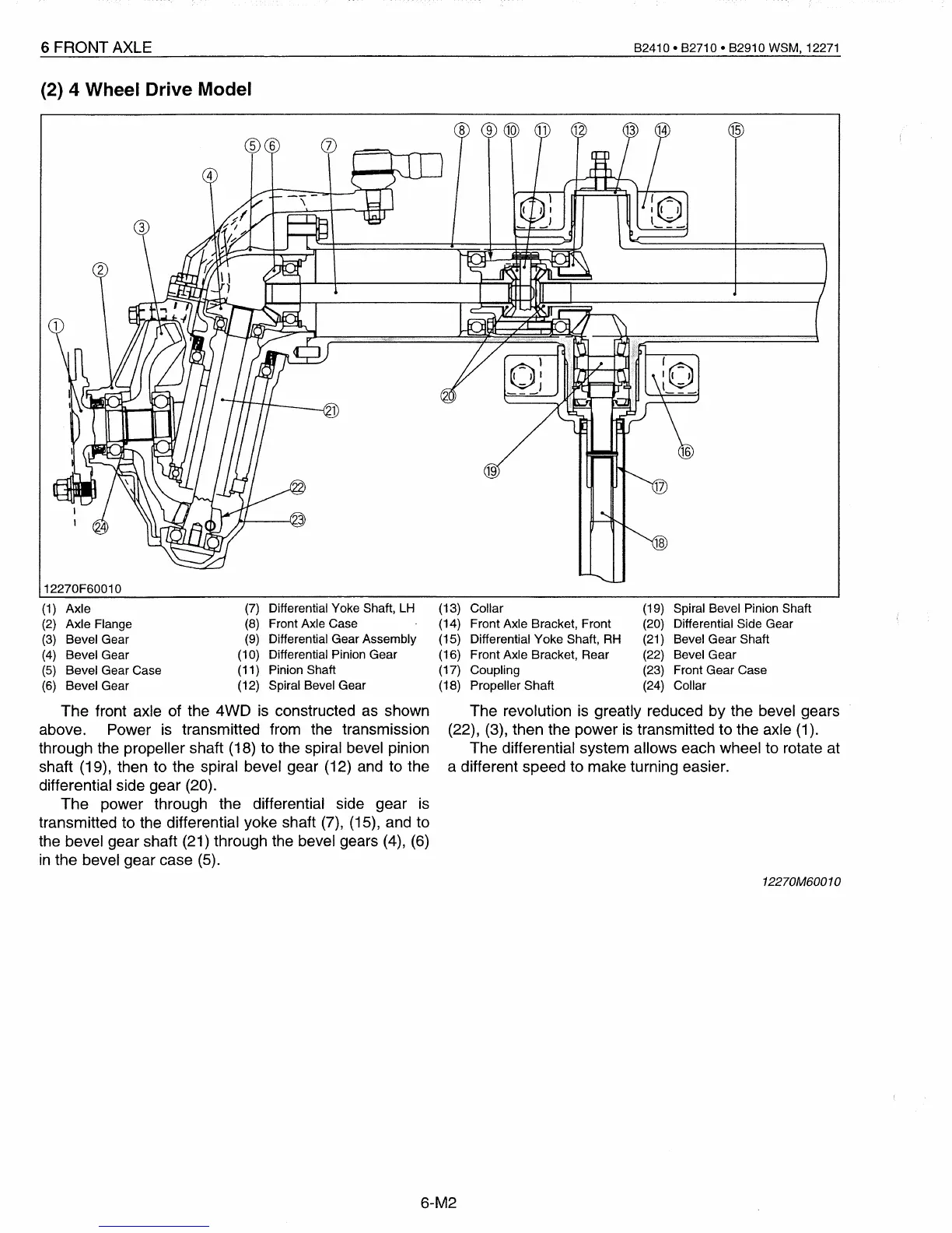
The front axle of the 4WD
is
constructed as shown
above. Power
is
transmitted from the transmission
through the propeller shaft (18) to the spiral bevel pinion
shaft (19), then to the spiral bevel gear (12) and to the
differential side gear (20).
The power through the differential side gear
is
transmitted to the differential yoke shaft
(7),
(15), and to
the bevel gear shaft (21) through the bevel gears (4), (6)
in
the bevel gear case
(5).
(13) Collar
(19)
Spiral Bevel Pinion Shaft
(14) Front Axle Bracket, Front
(20)
Differential Side Gear
(15) Differential Yoke Shaft,
RH
(21)
Bevel Gear Shaft
(16) Front Axle Bracket, Rear
(22)
Bevel Gear
(17) Coupling
(23)
Front Gear Case
(18) Propeller Shaft
(24)
Collar
The revolution
is
greatly reduced by the bevel gears
(22), (3), then the power
is
transmitted to the axle
(1).
The differential system allows each wheel to rotate at
a different speed to make turning easier.
12270M60010
6-M2
 Loading...


