B2410 • B2710 • B2910 WSM,
12271
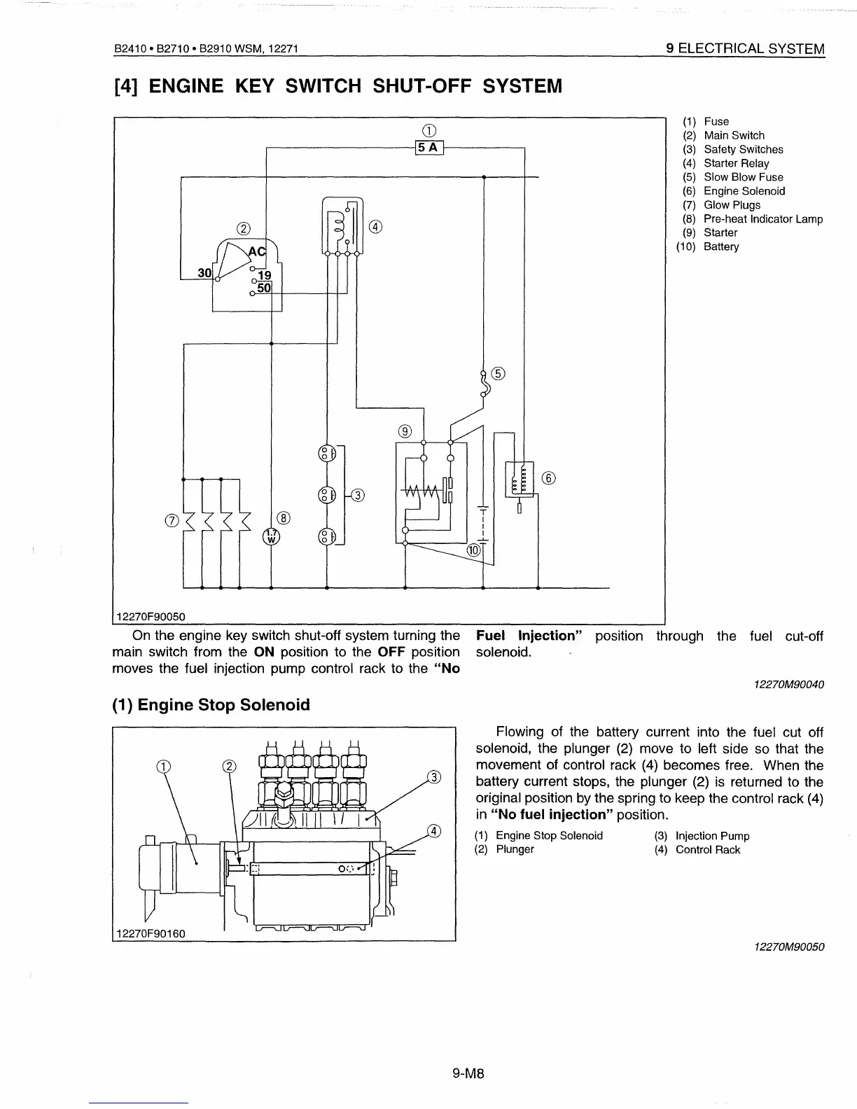
[4] ENGINE KEY SWITCH SHUT-OFF SYSTEM
9 ELECTRICAL SYSTEM
CD
(1
) Fuse
(2)
Main Switch
5A
(3)
Safety Switches
(4)
Starter Relay
(5)
Slow Blow Fuse
(6)
Engine Solenoid
I
(7)
Glow Plugs
0
(1)
(8)
Pre-heat Indicator Lamp
(9)
Starter
(10) Battery
®
12270F90050
®
®
T
I
I
I
-l-
@)
®
On
the engine key switch shut-off system turning the Fuel Injection" position through the fuel cut-off
main switch from the
ON
position to the OFF position solenoid.
moves the fuel injection pump control rack to the "No
12270M90040
(1) Engine Stop Solenoid
Flowing of the battery current into the fuel cut off
solenoid, the plunger
(2)
move to left side so that the
movement of control rack
(4)
becomes free. When the
battery current stops, the plunger (2)
is
returned to the
original position
by
the spring to keep the control rack
(4)
in
"No fuel injection" position.
(1)
Engine Stop Solenoid
(3)
Injection Pump
(2) Plunger
(4)
Control Rack
12270M90050
9-M8
 Loading...


