6 FRONT AXLE
B241
0 •
B2710·
B2910 WSM,
12271
12270P60030
(2) Disassembling Front Axle Assembly
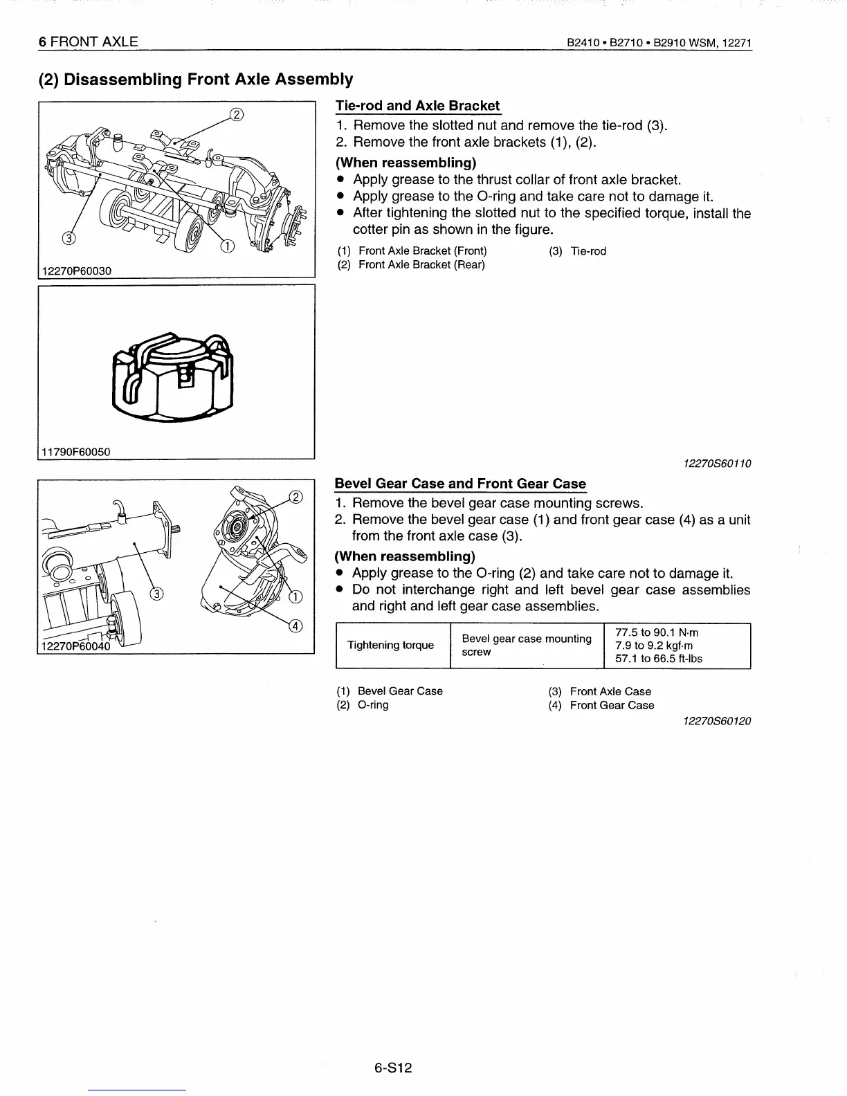
Tie-rod and Axle Bracket
1.
Remove the slotted nut and remove the tie-rod (3).
2.
Remove the front axle brackets (1), (2).
(When reassembling)
• Apply grease to the thrust collar of front axle bracket.
• Apply grease to the a-ring and take care not to damage
it.
• After tightening the slotted nut to the specified torque, install the
cotter pin as shown
in
the figure.
(1)
Front Axle Bracket (Front)
(3)
Tie-rod
(2)
Front Axle Bracket (Rear)
11790F60050
12270860110
Bevel Gear Case and Front Gear Case
1.
Remove the bevel gear case mounting screws.
2.
Remove the bevel gear case
(1)
and front gear case
(4)
as
a unit
from the front axle case (3).
(When reassembling)
• Apply grease to the a-ring (2) and take care not to damage
it.
•
Do
not interchange right and left bevel gear case assemblies
and right and left gear case assemblies.
Bevel gear case mounting
77.5 to
90.1
N·m
Tightening torque
7.9 to 9.2 kgf·m
screw
57.1 to 66.5 ft-Ibs
(1)
Bevel Gear Case
(2)
O-ring
6-812
(3)
Front Axle Case
(4)
Front Gear Case
12270860120
 Loading...


