Configuration Examples
444
M4100 Series Managed Switch
The combination of VID to FID and then FID to MSTI allocation defines a mapping of VIDs to
spanning tree instances, represented by the MST Configuration Table.
With this allocation we ensure that every VLAN is assigned to one and only one MSTI. The
CIST is also an instance of spanning tree with a MSTID of 0.
An instance might occur that has no VIDs allocated to it, but every VLAN must be allocated to
one of the other instances of spanning tree.
The portion of the active topology of the network that connects any two bridges in the same
MST region traverses only MST bridges and LANs in that region, and never bridges of any
kind outside the region, in other words, connectivity within the region is independent of
external connectivity
.
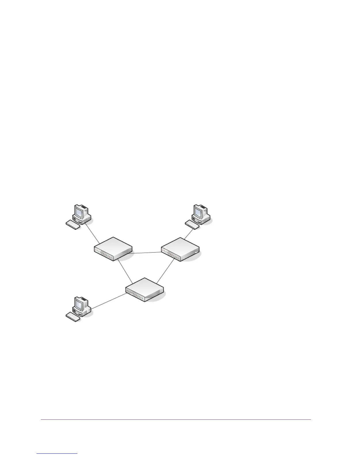
MSTP Sample Configuration
This example shows how to create an MSTP instance from a switch. The example network
has three different managed switches that serve different locations in the network. In this
example, ports 1/0/1–1/0/5 are connected to host stations, so those links are not subject to
network loops. Ports 1/0/6–1/0/8 are connected across switches 1, 2, and 3.
Ports 1/0/1 - 1/0/5
Connected to Hosts
Ports 1/0/1 - 1/0/5
Connected to Hosts
Ports 1/0/1 - 1/0/5
Connected to Hosts
Ports 1/0/6 - 1/0/8
Connected to Switch 2 and 3
Ports 1/0/6 - 1/0/8
Connected to Switch 1 and 3
1/0/1 - 1/0/5 Switch 1
Root Bridge
Switch 2
Switch 3
Ports 1/0/6 - 1/0/8
Connected to
Switch 2 and
Figure 2. MSTP configuration
Perform the following procedures on each switch to configure MSTP:
1. Use the VLAN Configuration screen to create VLANs 300 and 500.
See VLAN Overview on page 223.
2. Use the VLAN Membership screen to include ports 1/0/1 - 1/0/8 as tagged (T) or untagged
(U) members of VLAN 300 and VLAN 500.
See VLAN Overview on page 223.
 Loading...