ENGINE
M6060, M7060, WSM
1-S72
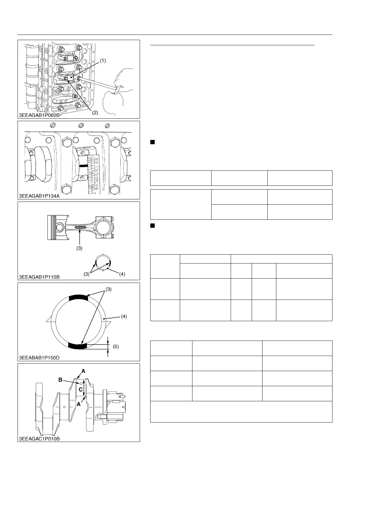
Oil Clearance between Crank Pin and Crank Pin Bearing
1. Clean the crank pin and crank pin bearing (4).
2. Put a strip of plastigauge on the center of the crank pin.
3. Install the connecting rod cap (1).
4. Tighten the connecting rod screws (2) to the specified torque.
5. Remove the connecting rod cap again.
6. Measure the width that it becomes flat with the scale to get the
oil clearance.
7. If the oil clearance is more than the allowable limit, replace the
crank pin bearing (4).
8. If the same dimension bearing is not applicable because of the
crank pin wear, replace it with an undersize one. Refer to the
table and figure.
• Do not put the Plastigauge into the crank pin oil hole.
• When you tighten the connecting rod screws (2), do not
move the crankshaft.
• To replace it with a specific STD service part, make sure the
crank pin bearing (4) has the same ID color (3) as the
connecting rod.
(Reference)
• Undersize dimensions of crank pin
9Y1210828ENS0113US0
Crank pin O.D. Factory specification
49.980 to 49.991 mm
1.9678 to 1.9681 in.
Oil clearance between
crank pin and crank pin
bearing
Factory specification
0.017 to 0.048 mm
0.00067 to 0.0018 in.
Allowable limit
0.20 mm
0.0079 in.
ID Color
Connecting rod Crank pin bearing
Large-end in. dia. Class
Part
code
Center wall thick
Blue
53.010 to
53.020 mm
2.0870 to 2.0874 in.
L
1G772-
22310
1.496 to 1.501 mm
0.05890 to 0.05909 in.
Without
color
53.000 to
53.010 mm
2.0867 to 2.0870 in.
S
1G772-
22330
1.491 to 1.496 mm
0.05870 to 0.05889 in.
Undersize
0.2 mm
0.008 in.
0.4 mm
0.02 in.
Dimension A
3.3 to 3.7 mm radius
0.13 to 0.14 in. radius
3.3 to 3.7 mm radius
0.13 to 0.14 in. radius
*Dimension B
1.0 to 1.5 mm relief
0.040 to 0.059 in. relief
1.0 to 1.5 mm relief
0.040 to 0.059 in. relief
Dimension C
49.780 to 49.791 mm dia.
1.9599 to 1.9602 in. dia.
49.580 to 49.591 mm dia.
1.9520 to 1.9524 in. dia.
The crank pin must be fine-finished to higher than Rmax = 0.8S
*Holes to be de-burred and edges rounded with 1.0 to 1.5 mm
(0.040 to 0.059 in.) relief.
(1) Connecting Rod Cap
(2) Connecting Rod Screw
(3) ID Color
(4) Crank Pin Bearing
(5) Center Wall Thick
 Loading...