ELECTRICAL SYSTEM
M6060, M7060, WSM
8-M17
2. STARTING SYSTEM
[1] SYSTEM OUTLINE AND ELECTRICAL CIRCUIT
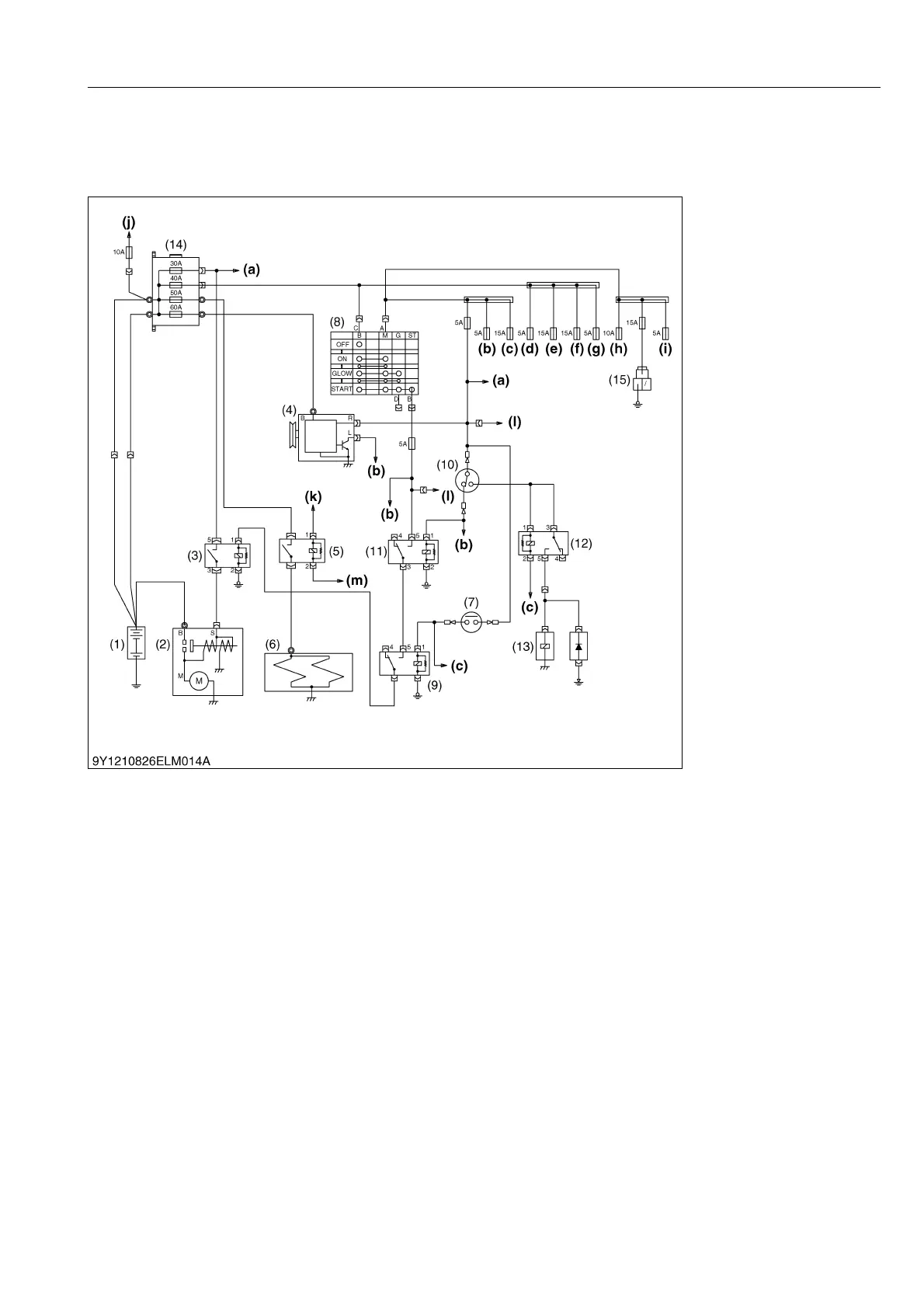
(1) ROPS Model
There are four key positions, "OFF", "ON", "GLOW" and "START" on the main key switch (8) as shown above.
When the main key switch (8) is set "ON", terminal AM of the main key switch (8) is connected to terminal M.
When the main key switch (8) is set to "START" under the condition that the hydraulic shuttle lever is neutral
position to transmission neutral safety switch (7) and the PTO switch (10) is turned OFF position. Terminal G of the
main key switch is connected to terminal M and terminal ST. Consequently, battery current flows to PTO switch (10),
coil of starter relay (3), PTO safety relay (11). (When the PTO switch is set to OFF, battery current flows PTO switch
(10) and coil of PTO safety relay (11).)
This actuates starter (2).
When the main switch is released after starting the engine, the main switch returns to "ON" automatically. This
stops the starter.
9Y1210828ELM0001US0
(1) Battery
(2) Starter Motor
(3) Starter Relay
(4) Alternator
(5) Glow Relay
(6) Glow Plug
(7) Transmission Neutral Safety
Switch
(8) Main Key Switch
(9) Neutral Relay
(10) PTO Switch
(11) PTO Safety Relay
(12) PTO Relay
(13) PTO Solenoid Valve
(14) Slow Blow Fuse
(15) Auxiliary Power Connector
(a) To Work Light
(b) To Meter Panel
(c) To Main ECU
(d) To Meter (Back Up)
(e) To Head Lamp, Tail Lamp
(f) To Flasher (Hazard)
(g) To ECU (Back Up)
(h) To Turn Signal, Stop Lamp
(i) To Transmission Control
(j) To CRS Power Relay
(k) To Engine ECU
(l) To CRS H
 Loading...