ELECTRICAL SYSTEM
M6060, M7060, WSM
8-S46
[12] LIGHTING SWITCHES AND FLASHER UNIT
(1) Combination Switch (ROPS Model)
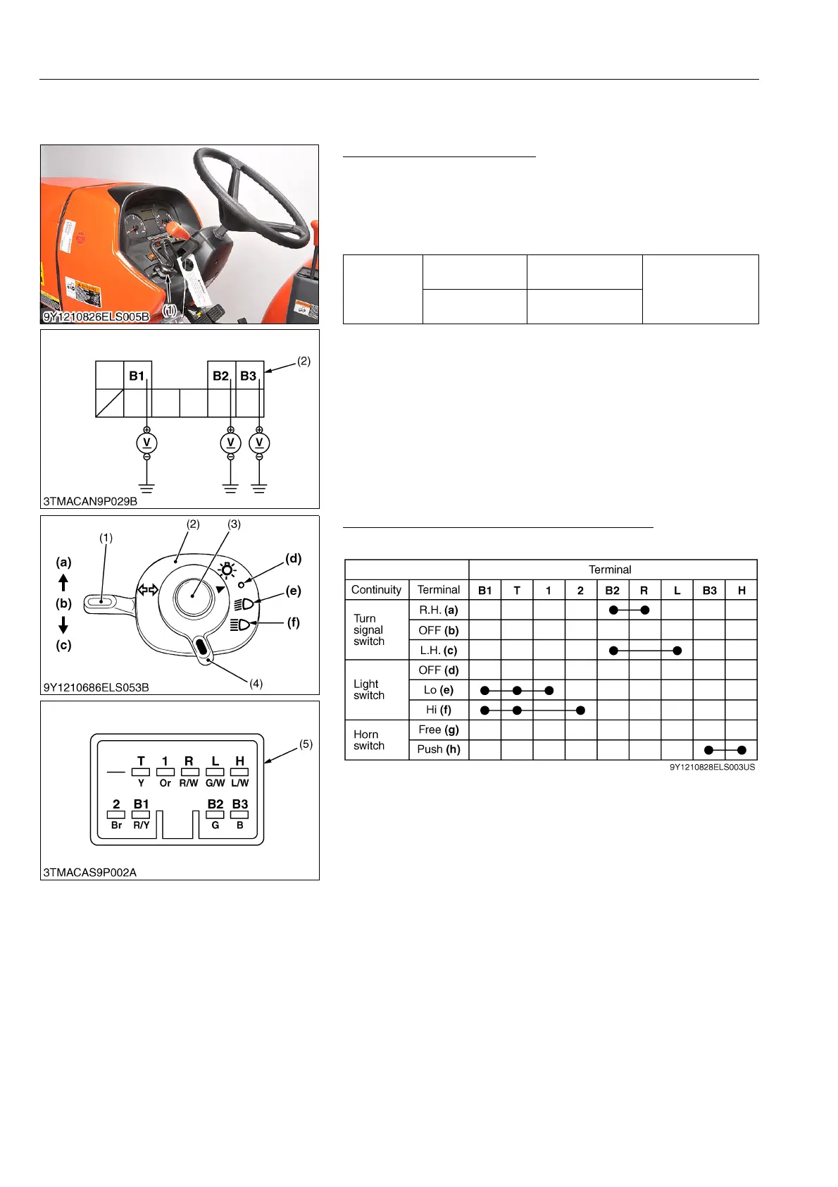
Checking Connector Voltage
1. Disconnect the combination switch connector.
2. Measure the voltage with voltmeter across the connector
terminal B1 and chassis, across the terminal B2 and chassis.
3. If the voltage differs from the battery voltage, the wiring harness,
fuses or main switch faulty.
9Y1210828ELS0084US0
Checking Light Switch and Turn Signal Switch
1. Test the continuity through the switch with an ohmmeter.
9Y1210828ELS0085US0
Voltage
Main switch at
"ON"
Terminal B1 –
Chassis
Approx. battery
voltage
Main switch at
"OFF"
Terminal B2 –
Chassis
(1) Combination Switch (2) Combination Switch Connector
(Wire Harness Side)
(1) Turn Signal Switch
(2) Combination Switch
(3) Horn Switch
(4) Light Switch
(5) Combination Switch Connector
(Switch Side)
(a) Right Turn
(b) OFF
(c) Left Turn
(d) OFF
(e) Head Light (Lo)
(f) Head Light (Hi)
(g) Free
(h) Push
 Loading...