HYDRAULIC SYSTEM
M6060, M7060, WSM
7-S20
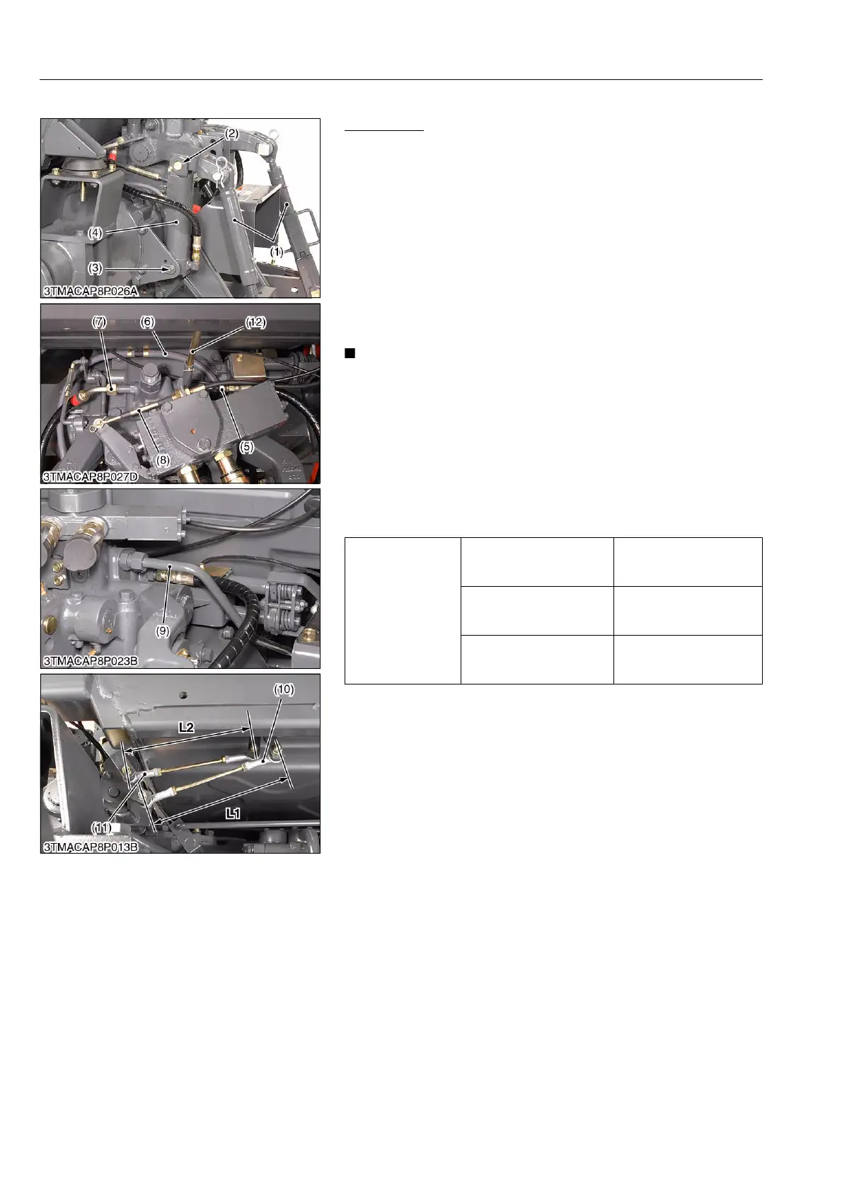
(2) Removing 3-point Hitch Hydraulic Block (CABIN Model)
Preparation
1. Park the tractor on a flat place.
2. Place the disassembling stand under the transmission case and
rear axle.
3. Remove the rear wheel (R.H.).
4. Remove the lift rods (1).
5. Disconnect the cylinder hoses (5), (7) and return hose (6).
6. Draw out the pins (2), (3) and remove the cylinder (4).
7. Remove the auxiliary control valve wire (8).
8. Remove the 3-point hitch delivery pipe (9).
9. Disconnect the position control rod (10) and draft control rod
(11).
10. Disconnect the lowering speed adjusting rod (12).
• Be careful not to damage the grease fitting when remove
the hydraulic cylinder pin.
(When reassembling)
• Apply grease to the grease fittings.
• Be careful not to damage the grease fittings when reassemble
the hydraulic cylinder.
• To assemble the auxiliary control valve wire, see page 7-S16.
• Be sure to fit the O-rings for auxiliary control valve.
• To assemble the position control rod (10) and the draft control
rod (11), see page 7-S9.
9Y1210828HYS0019US0
Tightening torque
Rear wheel mounting nut
260 to 304 N·m
26.5 to 31.0 kgf·m
191.8 to 224.2 lbf·ft
3-point hitch delivery pipe
retaining nut
107.9 to 117.7 N·m
11.0 to 12.0 kgf·m
79.6 to 86.8 lbf·ft
Cylinder hose retaining nut
45.1 to 53.0 N·m
4.6 to 5.4 kgf·m
33.3 to 39.1 lbf·ft
(1) Lift Rod
(2) Pin (Upper)
(3) Pin (Lower)
(4) Hydraulic Cylinder
(5) Cylinder Hose (R.H.)
(6) Return Hose
(7) Cylinder Hose (L.H.)
(8) Auxiliary Control Valve Wire
(9) 3-point Hitch Delivery Pipe
(10) Position Control Rod
(11) Draft Control Rod
(12) Lowering Speed Adjusting Rod
L1 : Position Control Rod Length
L2 : Draft Control Rod Length
 Loading...