FRONT AXLE
M6060, M7060, WSM
5-S6
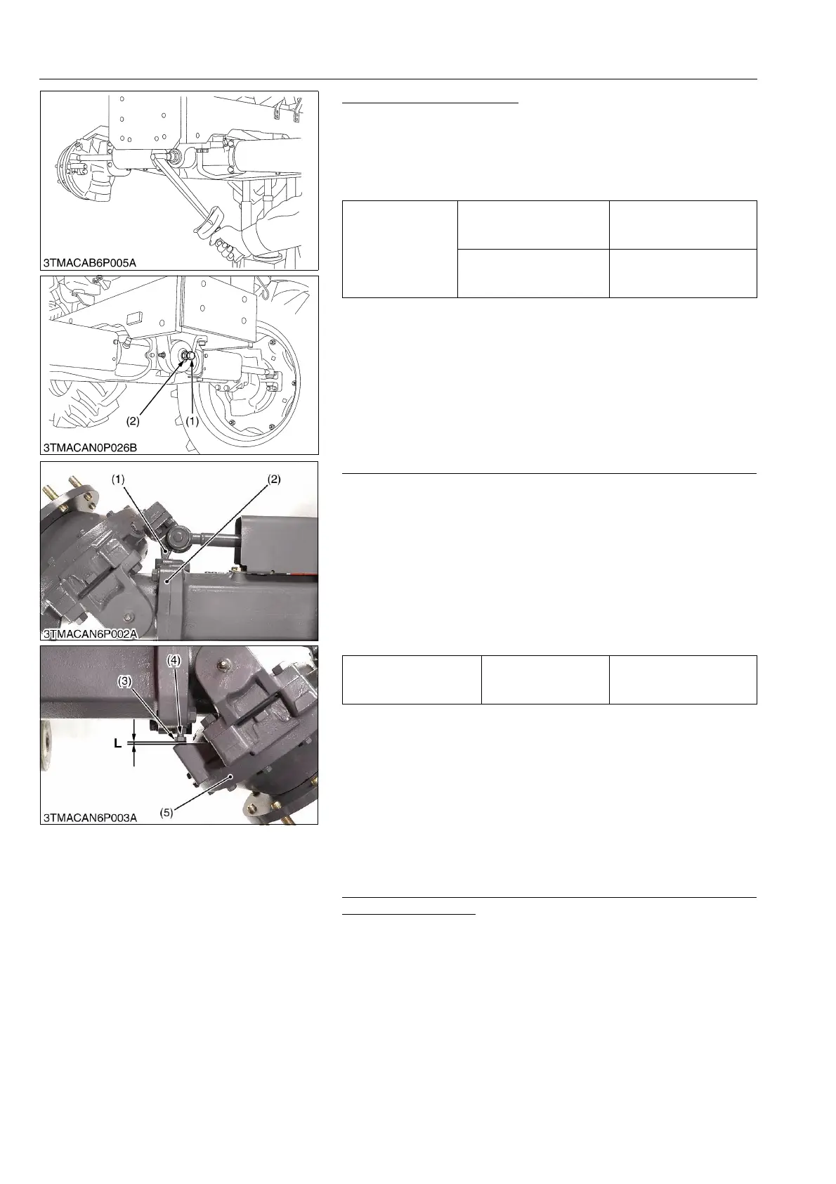
Adjusting Front Axle Pivot
1. Jack up the tractor body, then loosen the front axle rocking force
adjusting lock nut (2).
2. Screw in the adjusting screw (1) until seated, then tighten the
adjusting screw (1) with an additional 1/6 turn.
3. Retighten the lock nut (2).
9Y1210828FAS0006US0
Adjusting between Bevel Gear Case and Stopper [4WD Model]
1. Inflate the tires to the specified pressure.
2. Steer the wheels to the extreme right until the knuckle arm (1)
contacts with the bevel gear case (2).
3. If the knuckle arm (1) can not be contacted with the bevel gear
case (2), shorten the length of stopper (3).
4. Keeping the knuckle arm (1) contact with the bevel gear case
(2), make a specified length as shown in the table.
5. After adjustment, secure the stopper with the lock nut (4).
6. For adjusting the left steering angle, perform the same
procedure as mentioned in right steering angle.
9Y1210828FAS0007US0
[2] DISASSEMBLING AND ASSEMBLING
(1) Separating Front Axle [4WD Model]
Draining Front Axle Gear Case (Right and Left) and Front
Differential Case Oil
• See page G-37.
9Y1210828FAS0008US0
Tightening torque
Front axle rocking force
adjusting screw
20 to 29 N·m
2.0 to 3.0 kgf·m
15 to 21 lbf·ft
Front axle rocking force
adjusting lock nut
98.1 to 147 N·m
10.0 to 15.0 kgf·m
72.4 to 108 lbf·ft
(1) Adjusting Screw (2) Lock Nut
Clearance between
bevel gear case and
stopper (L)
Factory specification
Below
0.5 mm
0.02 in.
(1) Knuckle Arm
(2) Bevel Gear Case
(3) Stopper
(4) Lock Nut
(5) Front Gear Case
L : Clearance
 Loading...