HYDRAULIC SYSTEM
M6060, M7060, WSM
7-S21
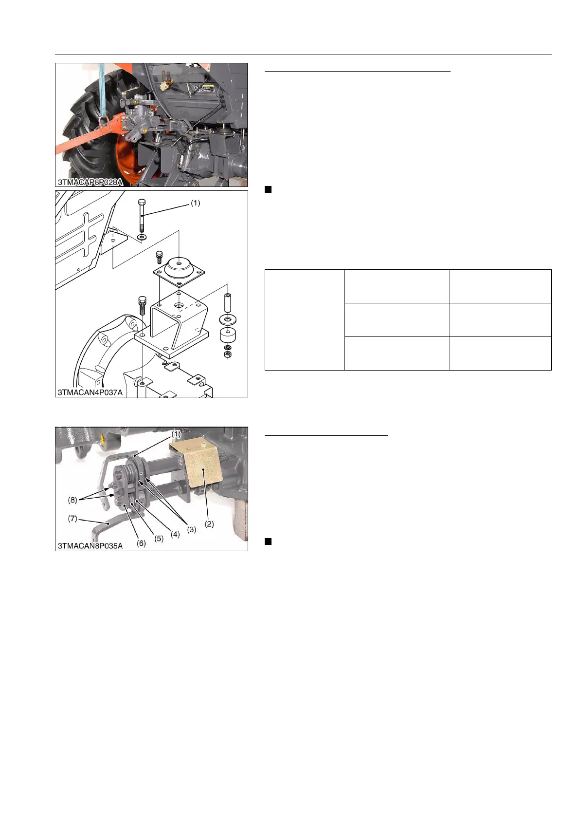
Removing 3-Point Hitch Hydraulic Block
1. Remove the rear cabin mounting bolts (1) and lift up the cabin
rear side approx. 38.0 to 50.0 mm (1.5 to 2.0 in.) then support
the cabin.
2. Remove the 3-point hitch hydraulic block mounting screws and
nuts.
3. Remove the 3-point hitch hydraulic block assembly.
(When reassembling)
• Apply liquid gasket (Three Bond 1206C or equivalent) to joint
face of transmission case and 3-point hitch hydraulic block.
• After reassembling the 3-point hitch hydraulic block
assembly to the tractor, be sure to adjust the position and
draft levers and position and draft feedback rods.
• 3-point hitch hydraulic block mounting screw has two
different length, be sure to assemble the original position.
• Be sure to assemble the cabin mount as shown figure.
9Y1210828HYS0020US0
[3] HYDRAULIC LINKAGE
Position and Draft Linkage
1. Remove the link cover (2).
2. Remove the nuts (8) then draw out the spring plates (6), springs
(5) and plate (4).
3. Tap out the roll pin then draw out the friction plates (3), draft
lever 1 (1) and position lever 1 (7).
(When reassembling)
• Be sure to assemble the friction plate to original position and
they are free for oil and dust.
• After assembling the linkage, adjust the position and draft
levers operating force and position and draft rods.
9Y1210828HYS0021US0
Tightening torque
Cabin mounting bolt and
nut (M14, 7T)
124 to 147 N·m
12.6 to 15.0 kgf·m
91.2 to 108 lbf·ft
3-point hitch hydraulic
block mounting screw
(M14, 9T)
166.7 to 196.1 N·m
17.0 to 20.0 kgf·m
123.0 to 144.7 lbf·ft
3-point hitch hydraulic
block mounting nut (M14,
7T)
123.6 to 147.1 N·m
12.6 to 15.0 kgf·m
91.1 to 108.5 lbf·ft
(1) Cabin Mounting Bolt
(1) Draft Lever 1
(2) Link Cover
(3) Friction Plate
(4) Plate
(5) Spring
(6) Spring Plate
(7) Position Lever 1
(8) Nut
 Loading...