ENGINE
M6060, M7060, WSM
1-S77
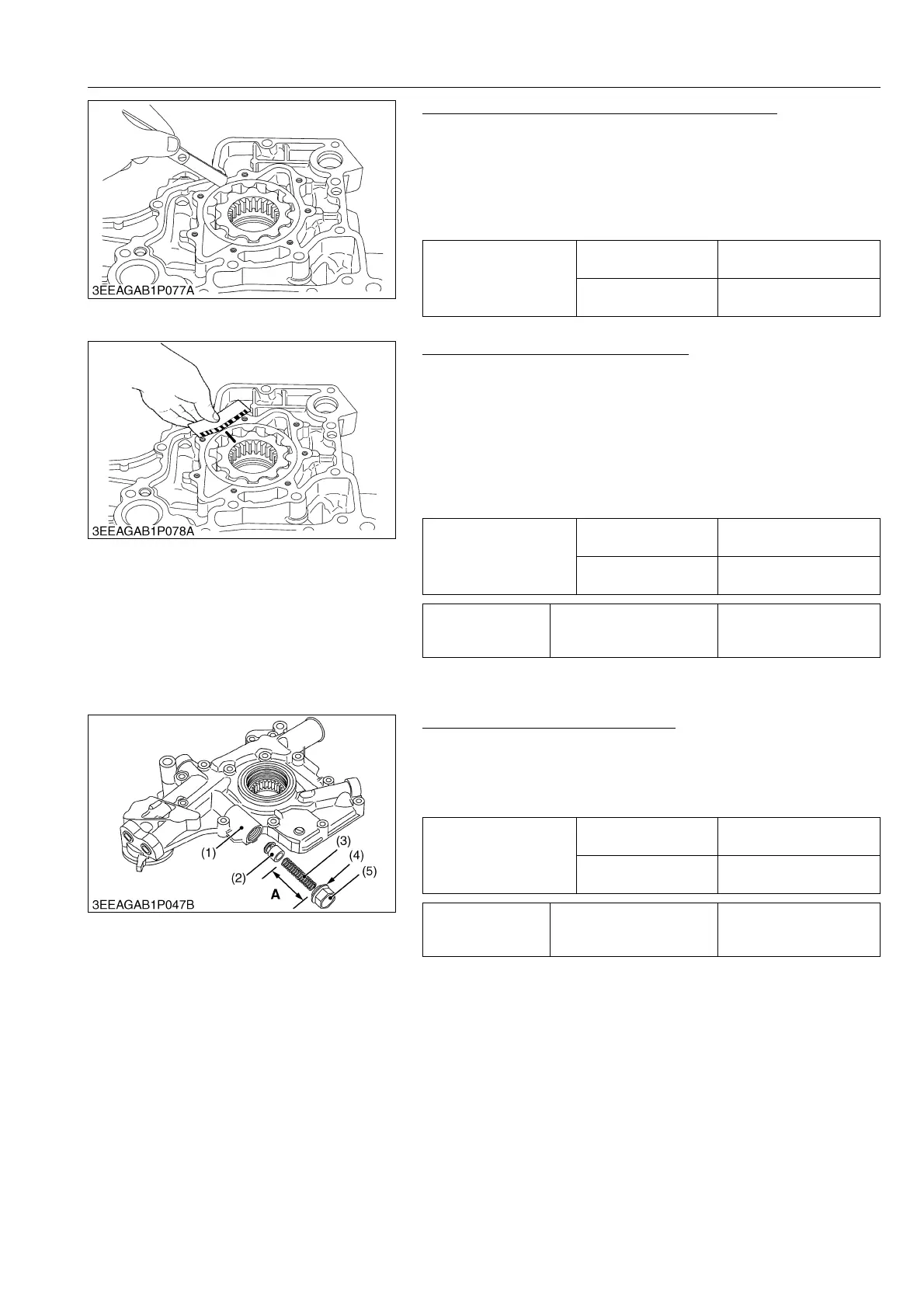
Clearance between Outer Rotor and Pump Body
1. Measure the clearance between the outer rotor and the pump
body with a feeler gauge.
2. If the clearance more than the allowable limit, replace the oil
pump rotor assembly.
3. If the clearance stays more than the allowable limit after
replacing the oil pump rotor assembly, replace the gear case.
9Y1210828ENS0122US0
Clearance between Rotor and Cover
1. Put a strip of plastigauge on the rotor face with grease.
2. Install the cover and tighten the screws with the specified
torque.
3. Remove the cover carefully.
4. Measure the width that plastigauge becomes flat with the scale
to get the oil clearance.
5. If the clearance is more than the allowable limit, replace oil
pump rotor assembly and the cover.
9Y1210828ENS0123US0
(7) Relief Valve
Free Length of Relief Valve Spring
1. Measure the free length "A" with vernier calipers. If the
measurement is less than the allowable limit, replace it.
2. Check the entire surface of the spring for scratches. Replace it,
if any.
9Y1210828ENS0124US0
Clearance between outer
rotor and pump body
Factory specification
0.100 to 0.184 mm
0.00394 to 0.00724 in.
Allowable limit
0.30 mm
0.012 in.
Clearance between rotor
and cover
Factory specification
0.025 to 0.075 mm
0.00099 to 0.0029 in.
Allowable limit
0.225 mm
0.00886 in.
Tightening torque Oil pump cover screw
7.9 to 9.3 N·m
0.80 to 0.95 kgf·m
5.8 to 6.8 lbf·ft
Free length "A"
Factory specification
60.0 to 60.5 mm
2.37 to 2.38 in.
Allowable limit
55.0 mm
2.17 in.
Tightening torque Relief valve retaining screw
69 to 78 N·m
7.0 to 8.0 kgf·m
51 to 57 lbf·ft
(1) Front Cover
(2) Relief Valve
(3) Spring
(4) Packing
(5) Relief Valve Retaining Screw
A : Free Length
 Loading...