HYDRAULIC SYSTEM
M6060, M7060, WSM
7-S31
6. SERVICING
[1] LIFT ARM AND TOP LINK BRACKET
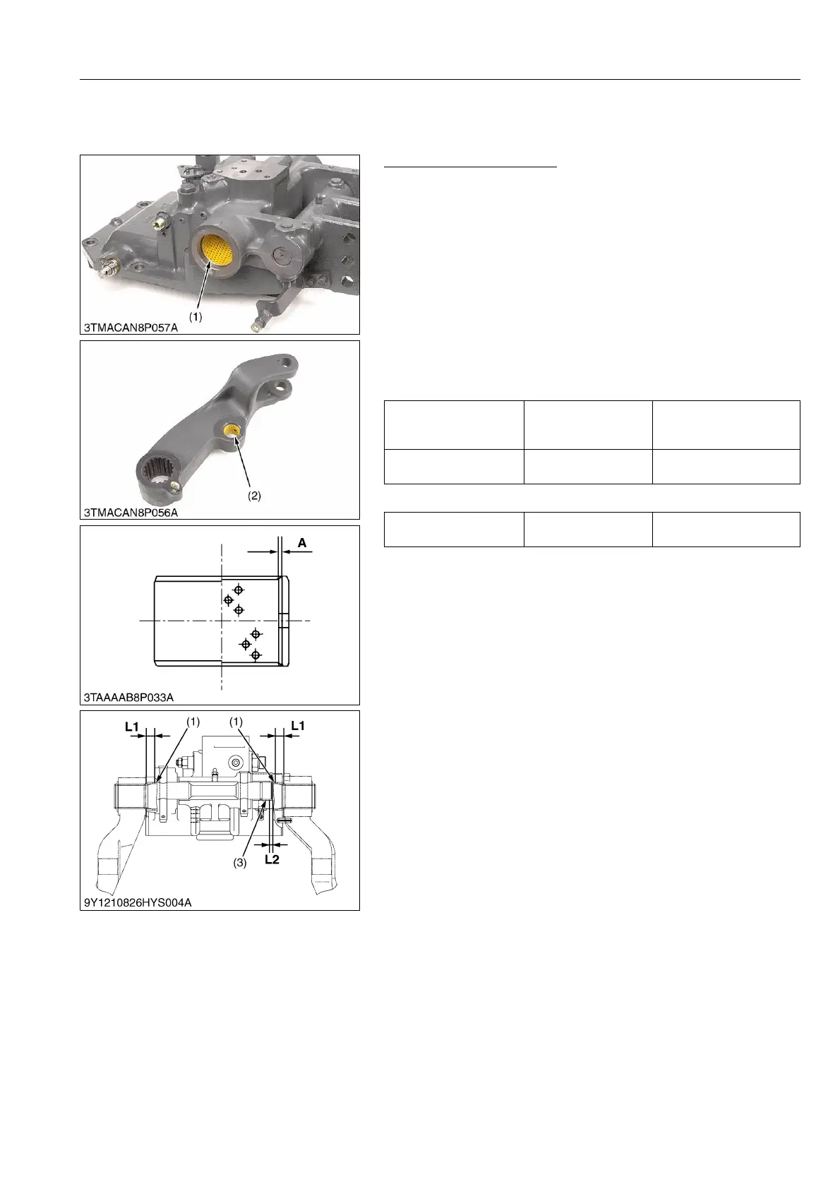
Lift Arm Support Bushing
1. Visually inspect the DX bushings for signs of wear or damage.
(The DX bushing tends to show concentrated wear.)
2. If the DX bushing is worn beyond the alloy portion (A), replace it.
(When installing)
• When press-fitting a new bushing with a press-fitting tool, see
page G-79.
• When press-fitting a new bushing, apply transmission fluid to
the lift arm support liner boss.
• When press-fitting a new bushing
– Lift arm support bushing's seam face to rear and hole face
to front and upper.
– Lift arm bushing's seam face to front and lower and hole
face to rear.
(Reference)
9Y1210828HYS0038US0
Press-fit location of the
lift arm support bushing
(L1)
Factory specification
15.0 mm
0.591 in.
Press-fit Location of the
Torsion Bar Bushing (L2)
Factory specification
6.0 mm
0.24 in.
Lift arm support and lift
arm bushing
Alloy thickness (A)
0.57 mm
0.0224 in.
(1) Lift Arm Support Bushing
(2) Lift Arm Bushing
(3) Torsion Bar Bushing
A : Alloy Thickness
L1 : Press-fit Location of the Lift Arm
Support Bushing
L2 : Press-fit Location of the Torsion
Bar Bushing
 Loading...