ELECTRICAL SYSTEM
M6060, M7060, WSM
8-S55
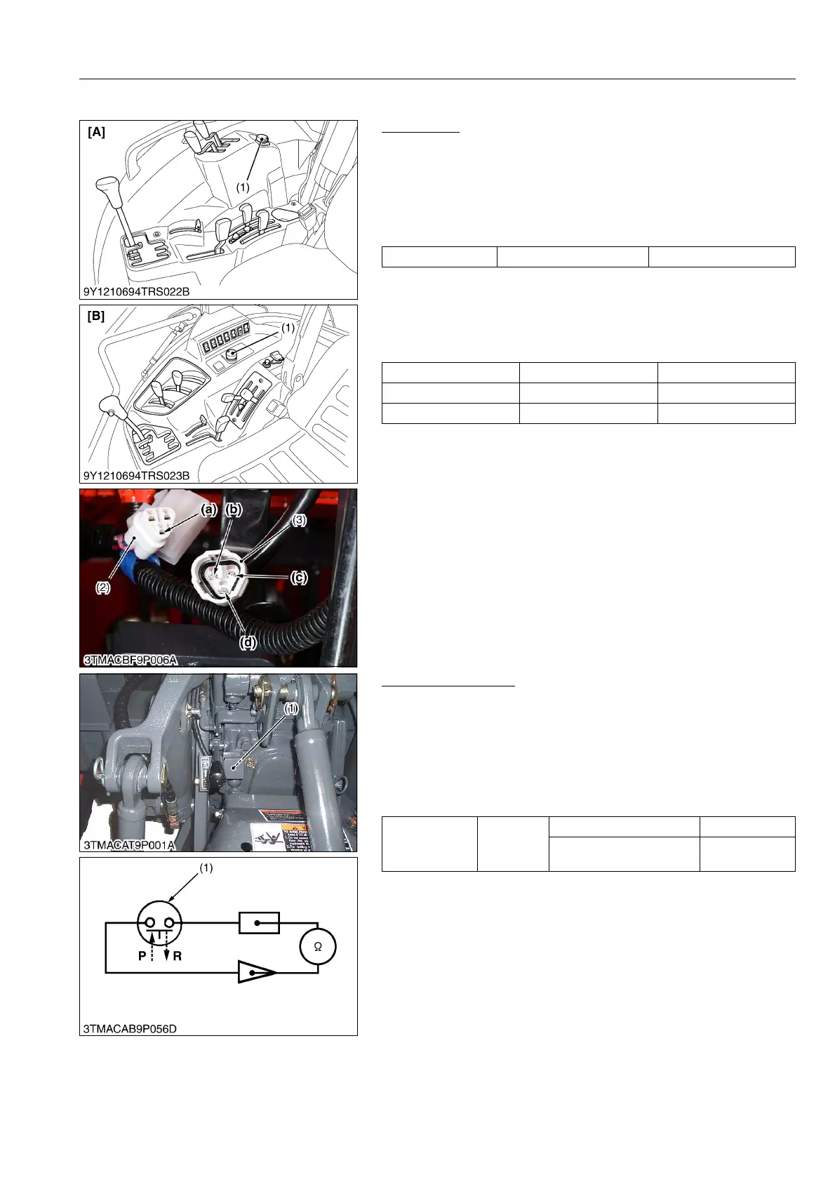
[15] PTO SWITCH
PTO Switch
1) Connector Voltage
1. Remove the PTO switch connector (3).
2. Turn the main switch ON position.
3. Measure the voltage across terminal 2 (a) and chassis.
4. If the voltage differs from battery voltage, the wiring harness,
fuse, or main switch is faulty.
2) PTO Switch Continuity
1. Remove the PTO switch connector (3).
2. Check the continuity with an ohmmeter across the terminal 1 (b)
and terminal 2 (d), terminal 2 (d) and terminal 3 (c).
3. If connection does not change, PTO switch is faulty.
9Y1210828ELS0122US0
PTO Change Switch
1) PTO Change Switch Continuity
1. Check the continuity with an ohmmeter across the switch
terminals.
2. If it does not conduct or any value is indicated when the switch
is pushed, the switch is faulty.
3. If infinity is not indicated when the switch is released, the switch
is faulty.
9Y1210828ELS0123US0
Voltage Terminal 2 – Chassis Approx. battery voltage
Position Terminal 1 – terminal 2 Terminal 2 – terminal 3
OFF 0 Ω Infinity
ON Infinity 0 Ω
(1) PTO Switch
(2) Harness Connector
(3) PTO Switch Connector
(a) Terminal 2 (Harness)
(b) Terminal 1
(c) Terminal 3
(d) Terminal 2 (PTO Switch)
[A] ROPS Model
[B] CABIN Model
Resistance
(Across switch
terminals)
Reference
value
When switch is pushed "P" 0 Ω
When switch is released
"R"
Infinity
(1) PTO Change Switch P: Pushed
R: Released
 Loading...