1
PANEL DESCRIPTION
1-7
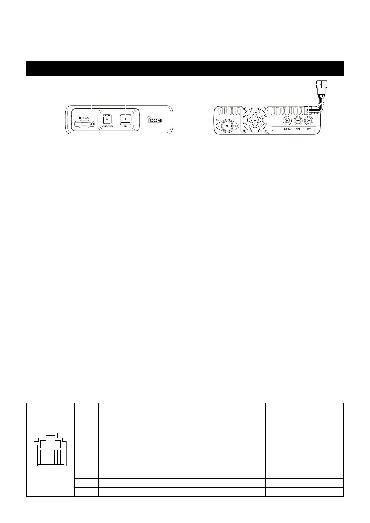
Mainunit—Frontandrearpanels
q w e r t y u i
o
q SD CARD SLOT [SD CARD]
Insert an SD card (purchase separately). (p. 9-4)
w CONTROLLER CONNECTOR [CONTROLLER]
Connects to the Controller using the supplied control
cable.
e MICROPHONE CONNECTOR [MIC]
Plug in the supplied microphone (HM-207) or the op-
tional microphone (HM-154).
r ANTENNA CONNECTOR
Connect a 50 ø impedance of antenna with a PL-
259 connector.
The transceiver has a built-in duplexer, so you can
use a 144 and 430 MHz dual-band antenna without
needing an external duplexer.
t COOLING FAN
The cooling fan for heat dissipation.
You can select the Fan control option in the Menu
screen; automatically starts to rotate when you be-
gin transmitting, or continuously rotates from power
ON.
y DATA JACK [DATA]
Connect a PC through the optional data communica-
tion cable, for cloning (p. 13-12) or low-speed data
communication (p. 7-15) in the DV mode.
u EXTERNAL SPEAKER JACK 1 [SP1]
i EXTERNAL SPEAKER JACK 2 [SP2]
Connect to an 8 ohm external speaker. ➥
• When you connect external speakers to [SP1]
and [SP2], the A band (left side display) audio
is heard from [SP1] and the B band (right side
display) audio is heard from [SP2].
• When you connect an external speaker to [SP1],
the A and B band audio is heard from [SP1]. In
this case, the internal speaker is disabled.
• When you connect an external speaker to [SP2],
the A band (left side display) audio is heard from
the internal speaker and the B band (right side
display) audio is heard from the external speak-
er.
The [SP2] jack is used for external control of the ➥
transceiver.
• Connect a PC, using the optional CT-17
c i -v
l e v e l c o n v e r t e r , for external control of the
transceiver.
• Use for the transceive function with another Icom
CI-V transceiver or receiver. When the transceive
function is set to ON, changing the frequency,
operating mode and so on, on the ID-5100A/E
automatically changes those settings on other
Icom transceivers or receivers, and vice versa.
oDCPOWERSOCKET[DC13.8V]
Connect 13.8 V DC power source through the sup-
plied DC power cable.
D Microphoneconnectorinformation
MIC
PINNo.
NAME DESCRIPTION SPECIFICATIONS
Front panel view
1 8 V +8 V DC output. Maximum 10 mA
2
MIC U/D Frequency Up/Down
UP: Ground
DN: Ground through 470 ˘
3
M8V SW
HM-207 connection
Grounds when the HM-207 is connected.
—
4 PTT
PTT input Ground for transmission
5
MIC E Microphone ground —
6 MIC
Microphone input —
7
GND PTT ground —
8
DATA IN When the HM-207 is connected; inputs HM-207 data —

 Loading...


